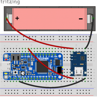
Charging the Battery
The battery is rechargeable and when charged, uses 3.7 volts of electricity to power your microcontroller and sensors. To charge the battery, we need to use the power from the microcontroller when it is plugged into the computer. We can then send the electricity to the battery for it to charge using the USB charger board included in your kit.

1. Start with your microcontroller connected to your breadboard and unplugged from your computer so it is not powered on.
2. Insert the battery into the battery holder so that the positive side, indicated by the “+” symbol, is on the side of the holder with the red wire, and the negative side of the battery is on the side of the holder with the black wire.
3. Using your breadboard to connect wires, start by connecting the red wire from the battery holder to the wire coming from the pin labeled “BAT+” on the charger.
4. Connect the black wire from the battery holder to the wire coming from the pin labeled “BAT-” on the charger.
5. Connect the wire from the pin labeled “IN-” on the charger to one of the “GND” pins on your microcontroller.
6. Connect the wire from the pin labeled “IN+” on the charger to the pin labeled “USB” on your microcontroller.
7. Double-check your connections, then plug in your microcontroller to your computer using the USB cable. The microcontroller will not be able to be accessed from your computer while the battery is charging. A red light will appear on the charger to indicate that the battery is charging. A blue light will appear on the charger to indicate that the battery is charged.
