This tutorial provides instructions for how to prepare your own PublicSensors kits. It provides instructions for soldering various components and optional instructions for assembling everything into an organizer for best use in a classroom setting. For sensor builders working independently, these later steps may not be necessary.
As a reminder, the following materials are PublicSensors kit components. Click icons for suggested links to purchase materials. Materials may be available cheaper in bulk at other distributed than those suggested. Some components require assembly prior to use. Others will be ready to use straight from the packaging.
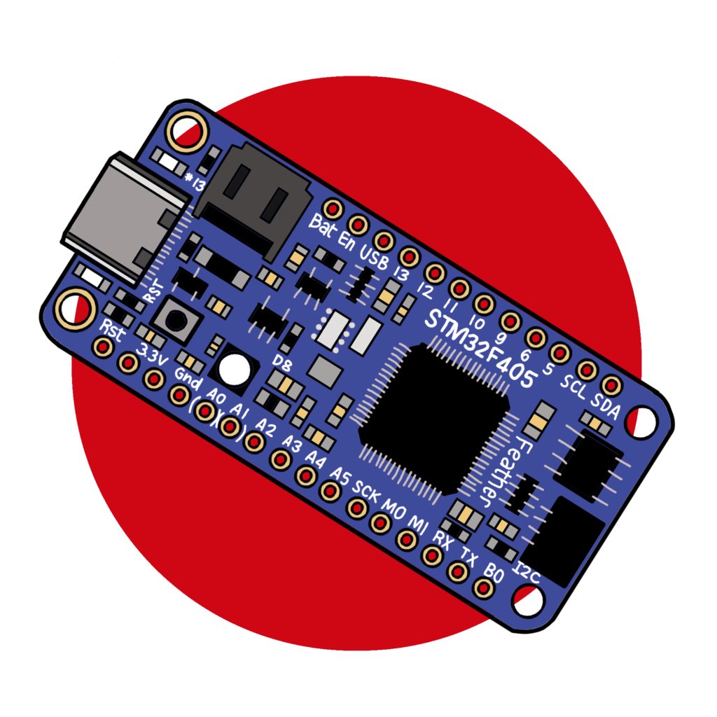
STM32F405 Microcontroller (1)
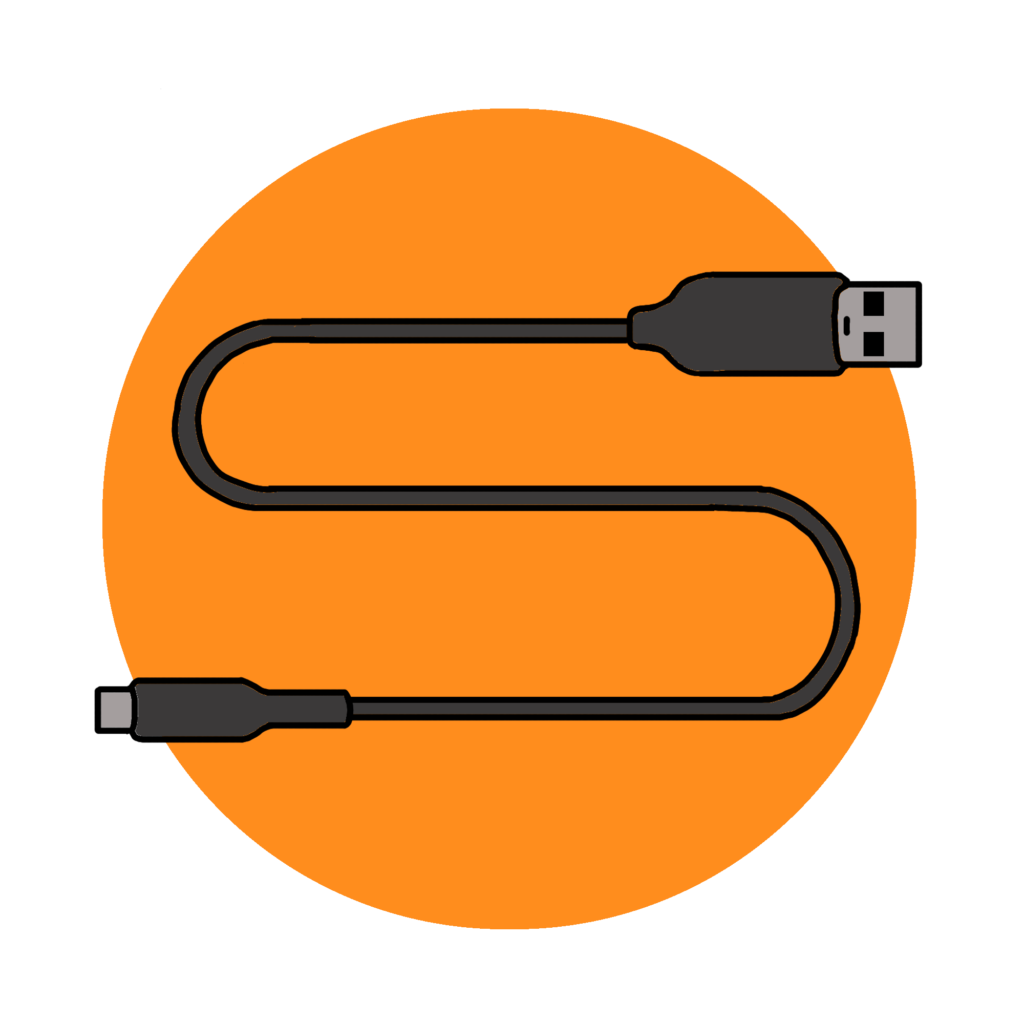
USB to USB-C Cable (1)
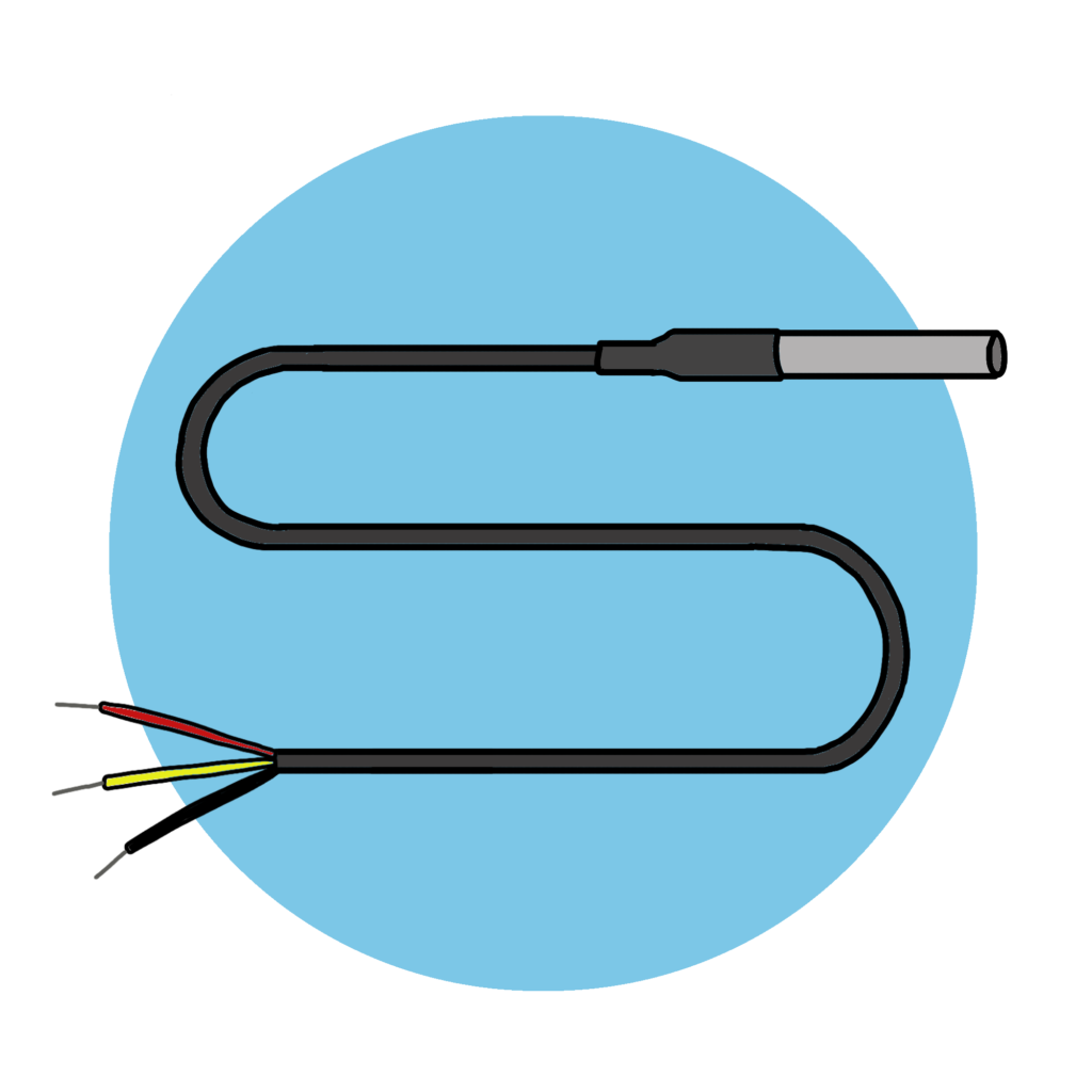
DS18B20 Temperature sensor (1)
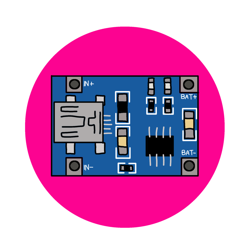
TP4056 Battery charger (1)
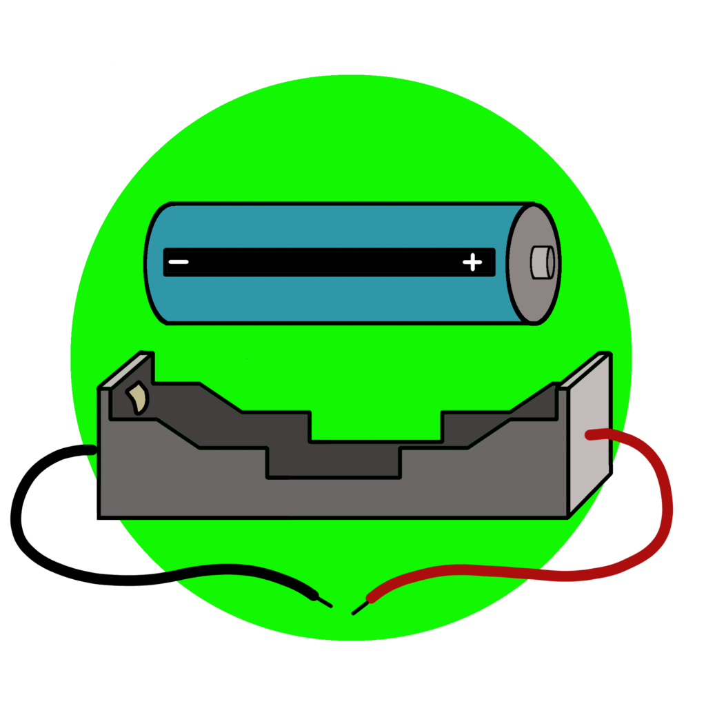
3.7V 18650 Li ion Battery and holder (1 each)
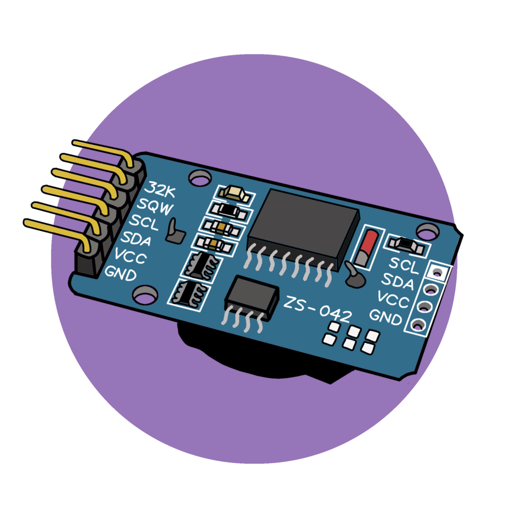
DS3231 Real time clock (1)
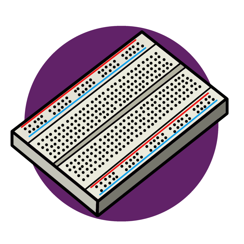
Half sized Breadboard (1)
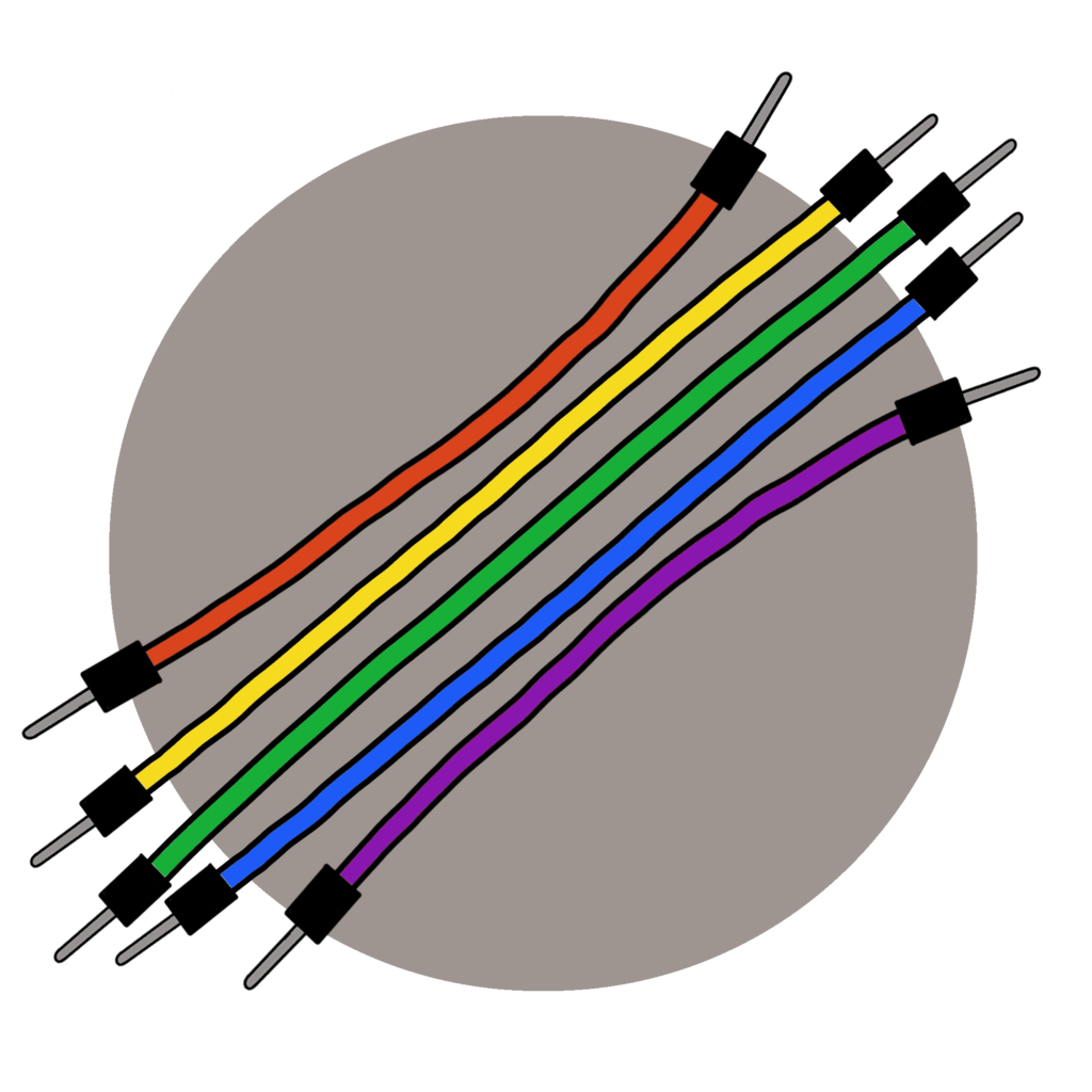
4" Jumper wires (20 M/M, 20 M/F)
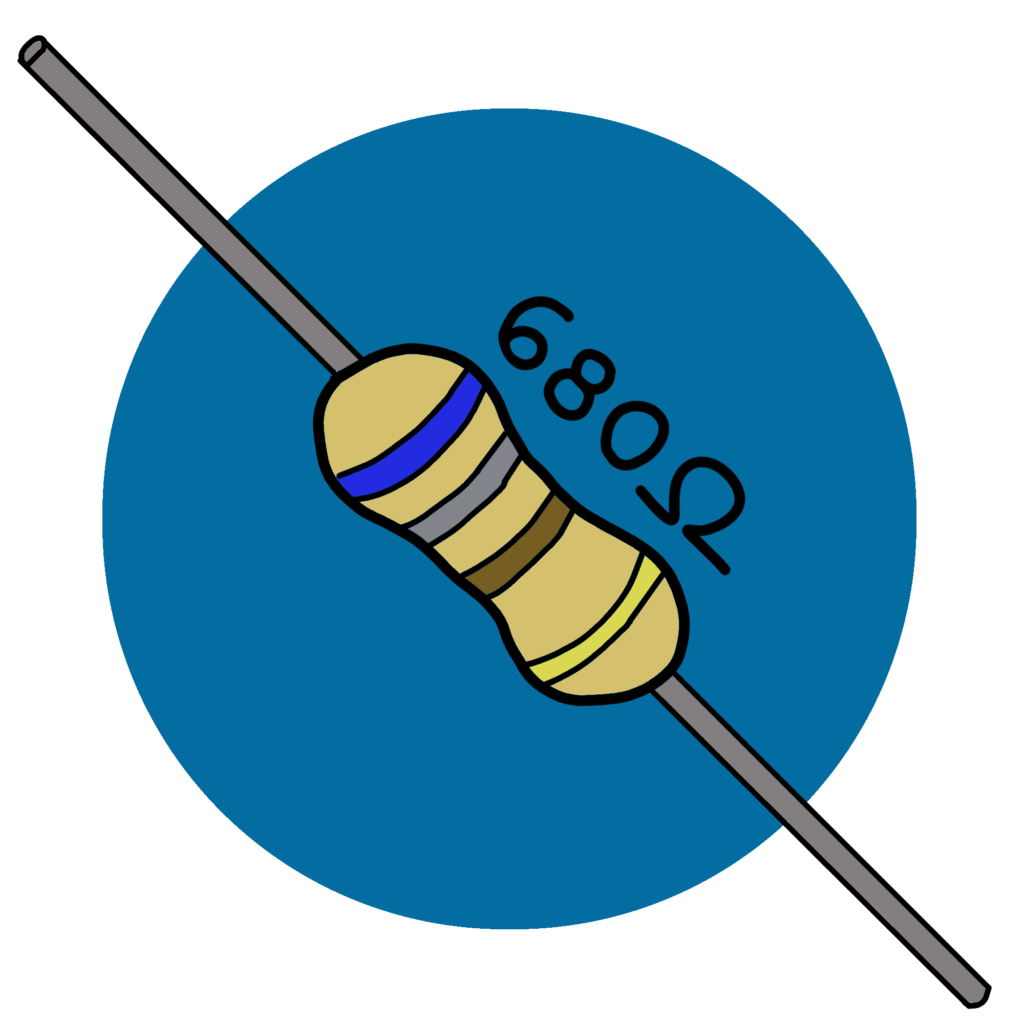
680 ohm resistor (2)
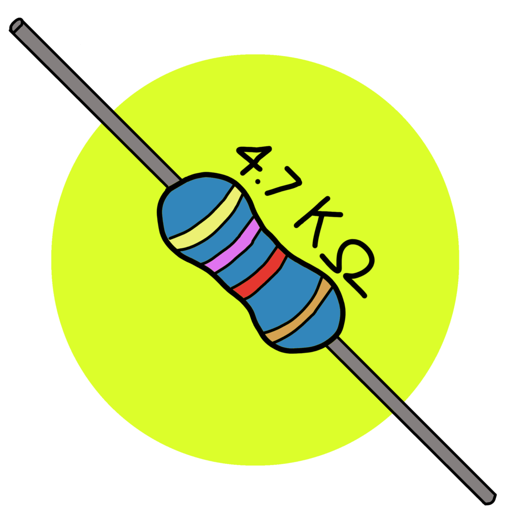
4.7K ohm resistor (2)
220K ohm resistor (2)
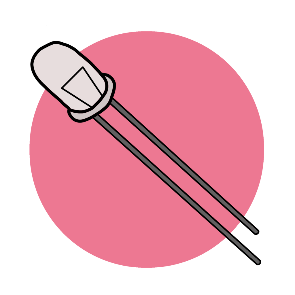
5mm LED (2)
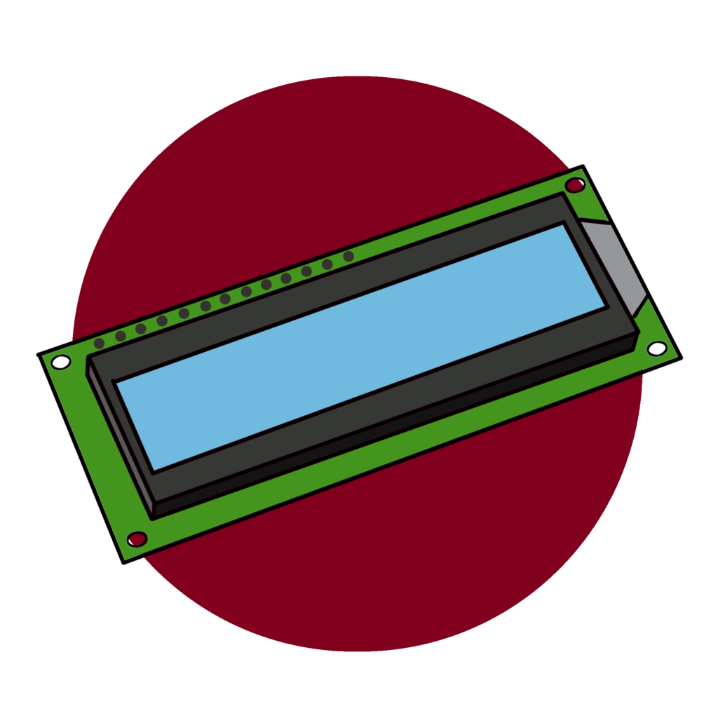
I2C 1602 LCD Screen (1)
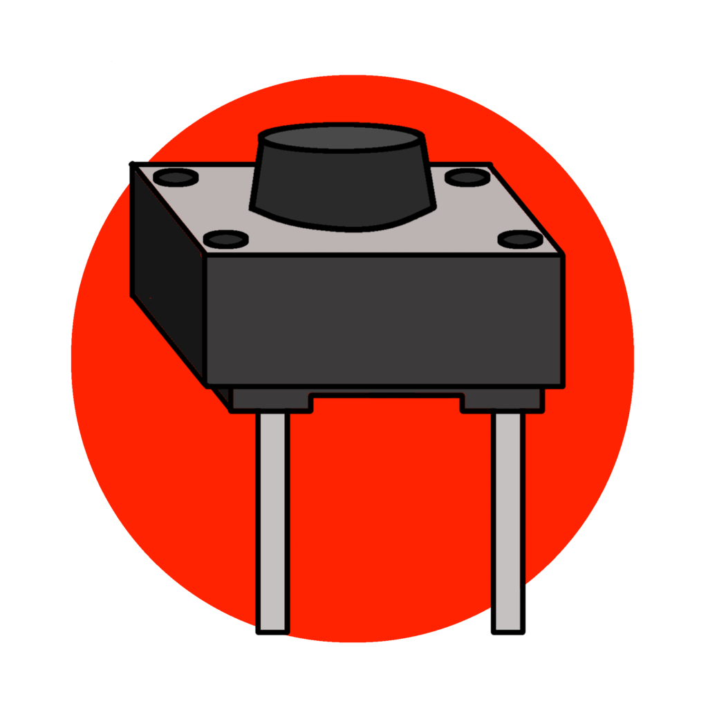
2 Pin Push Button (1)
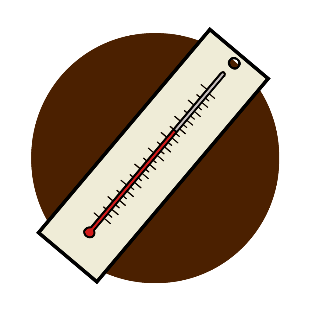
Simple Glass Thermometer (1)
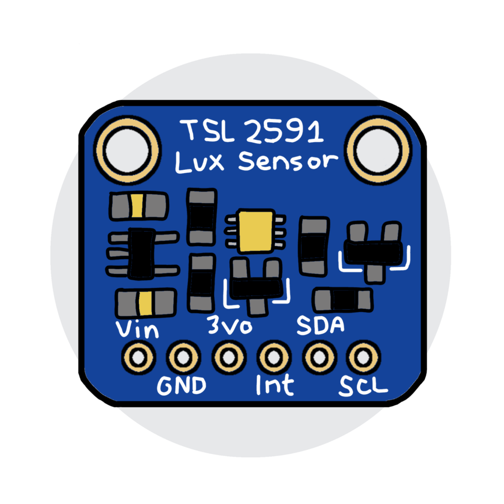
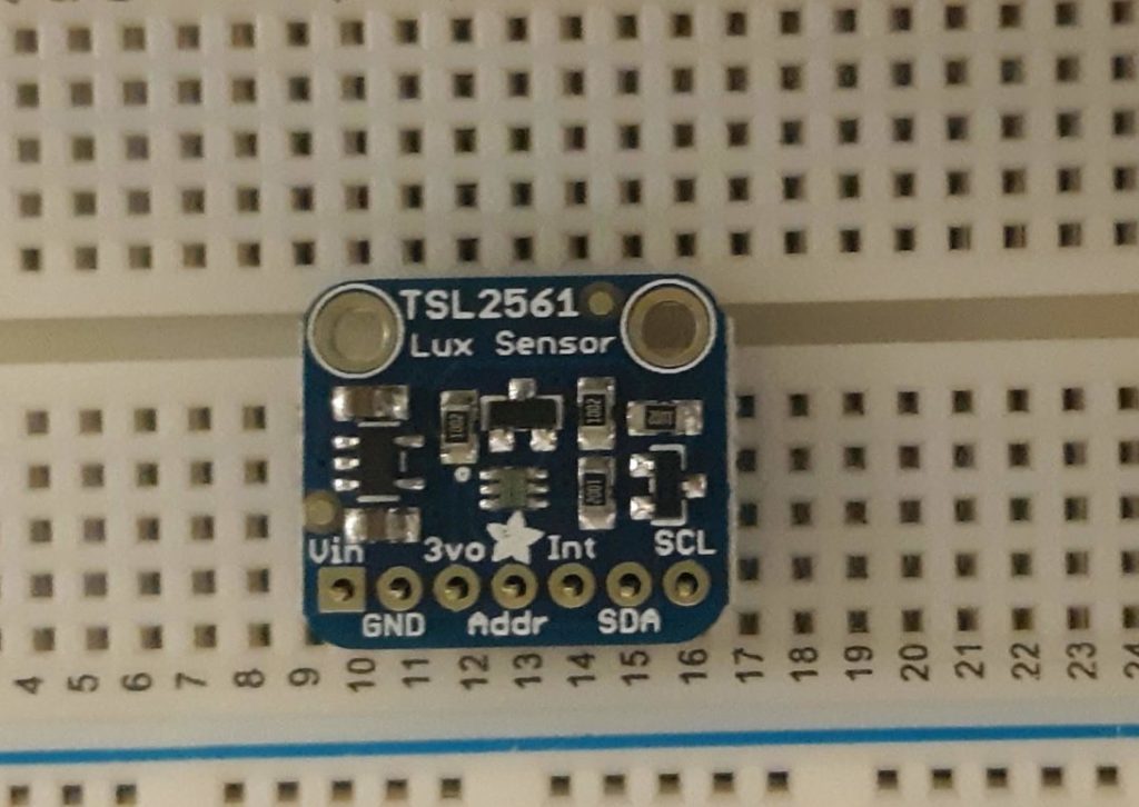
TSL25X1 Light sensor (1)
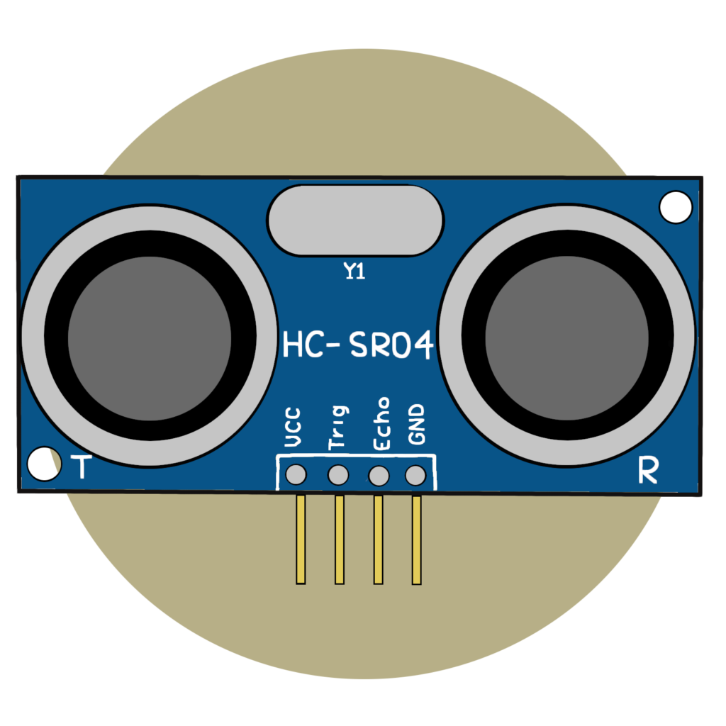
HC-SR04 Acoustic sensor (1)
6-pin Micro Slide Switch
1. Prepare the Microcontroller
These sections guide you through soldering header pins onto your microcontroller, formatting it with firmware, and transferring necessary Python files to it.
This section requires you to solder header pins on to the microcontroller. Header pins are needed to attach the microcontroller to a breadboard for circuit building.
If you are new to soldering, check out this video that introduces the skill and practice before trying to solder your microcontroller.
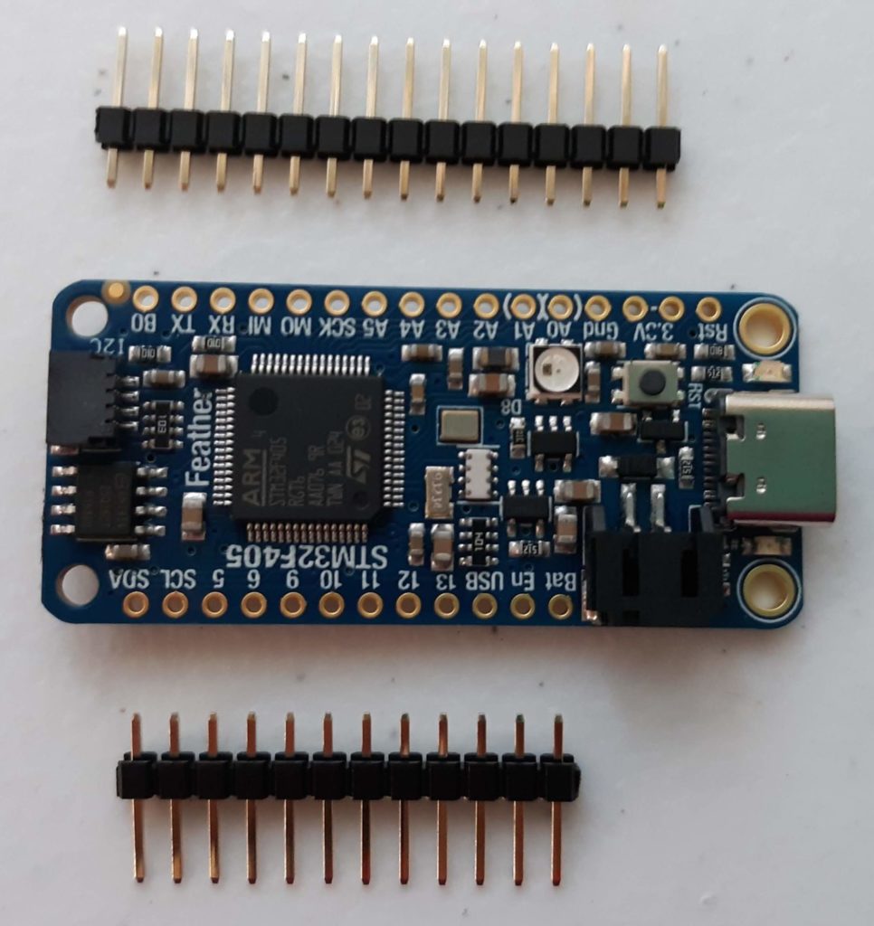
Header pins typically come with the microcontroller and you can use small pliers to break off the necessary lengths as shown in the photo to the right (Figure 1.1).
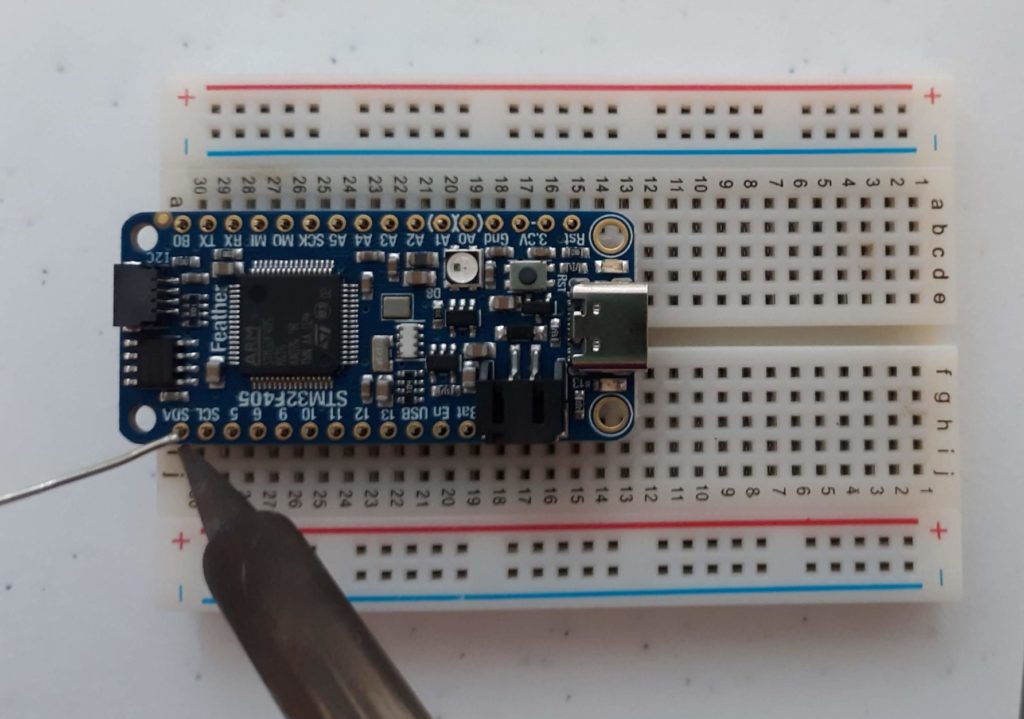
Use a breadboard to secure the pins and microcontroller as shown in the steps below.
Figure 1.1
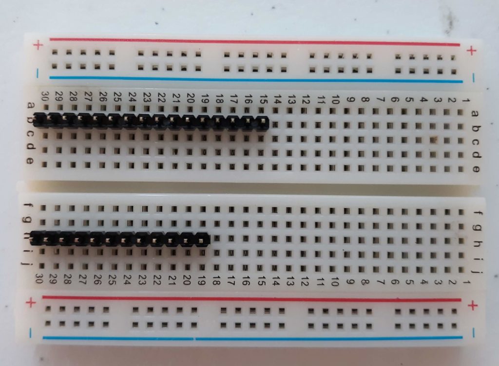
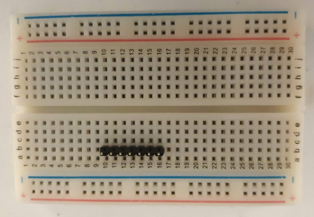
1. Place header pins on breadboard
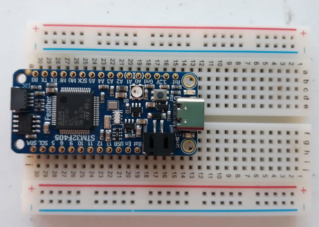
2. Position microcontroller on top on header pins
3. Solder pins in place
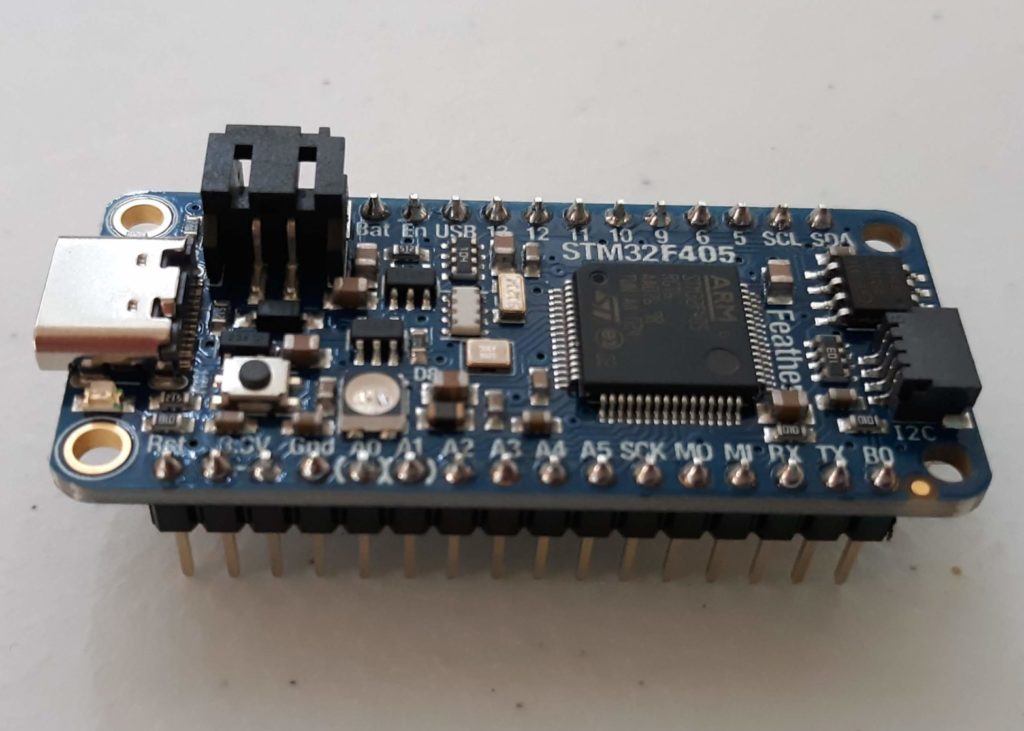
4. Remove microcontroller from breadboard
Figure 1.2
Figure 1.3
Figure 1.4
Figure 1.5
Upload Firmware to the Microcontroller
Below are instructions for one method to install the micropython firmware on to the microcontroller which will work using Windows, Mac, and Linux computers. For additional details and other installation methods, see the instructions from Adafruit.
1. Download and install the STM32CubeProgrammer. You will need to register and will get an email confirmation with the link to download the software.
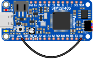
2. Connect Pin B0 to one of the 3.3V pins using a Female/Female jumper directly attached to the headers or via the breadboard.
3. Connect the microcontroller to your computer using the USB cable and launch STM32CubeProgrammer.
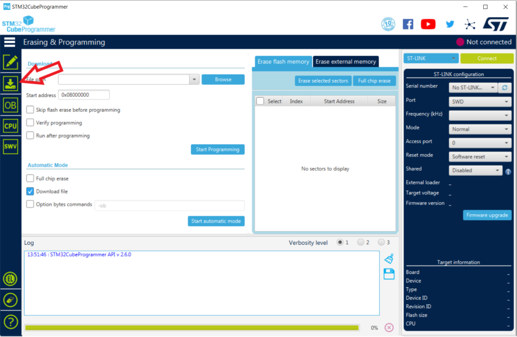
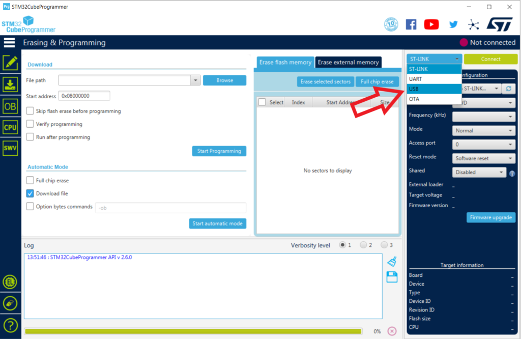
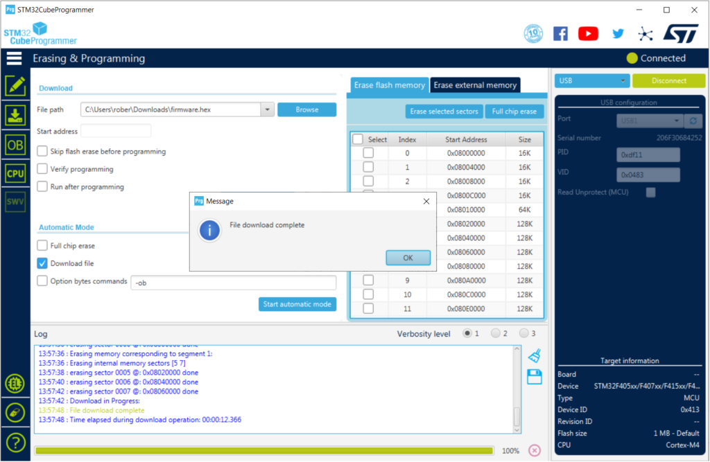
4. Select the Erasing & Programming tab.
5. To connect to the microcontroller, first select USB from the connection drop down menu.
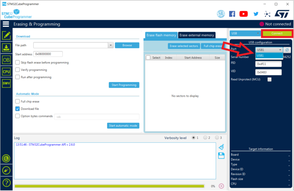
6. In the Port menu, select the available USB connection. If the microcontroller is detected, the serial number of the device will update.
7. Click on the Connect button.
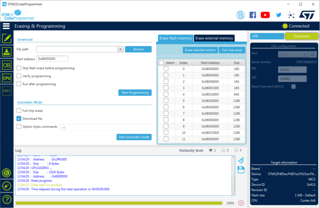
After connecting, the programmer will read through the microcontroller’s flash memory.
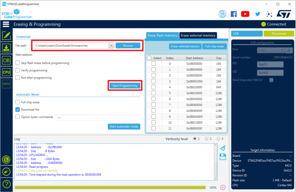
8. Select the firmware file. The .hex file can be downloaded from the PublicSensors GitHub page. Optional: By selecting Verify Programming, the software will check that the firmware works once uploaded. Run after programming will reset the microcontroller and connect to it without the bootloader, automatically disconnecting it from STM32CubeProgrammer.
9. Click on Start Programming to update the firmware. The software will be begin by erasing the flash memory on the microcontroller then proceed to upload the firmware.
Once the upload is complete, you can disconnect and close the programmer.
Transfer Python Files to the Microcontroller
To transfer Python file to your microcontroller, you will need to download the files from the PublicSensors GitHub page and save them to your microcontroller. See our GitHub instructions for more detail.
2. Additional Soldering
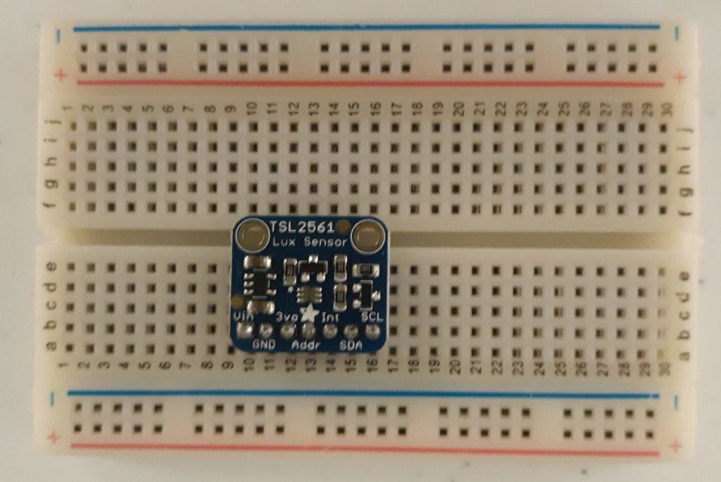
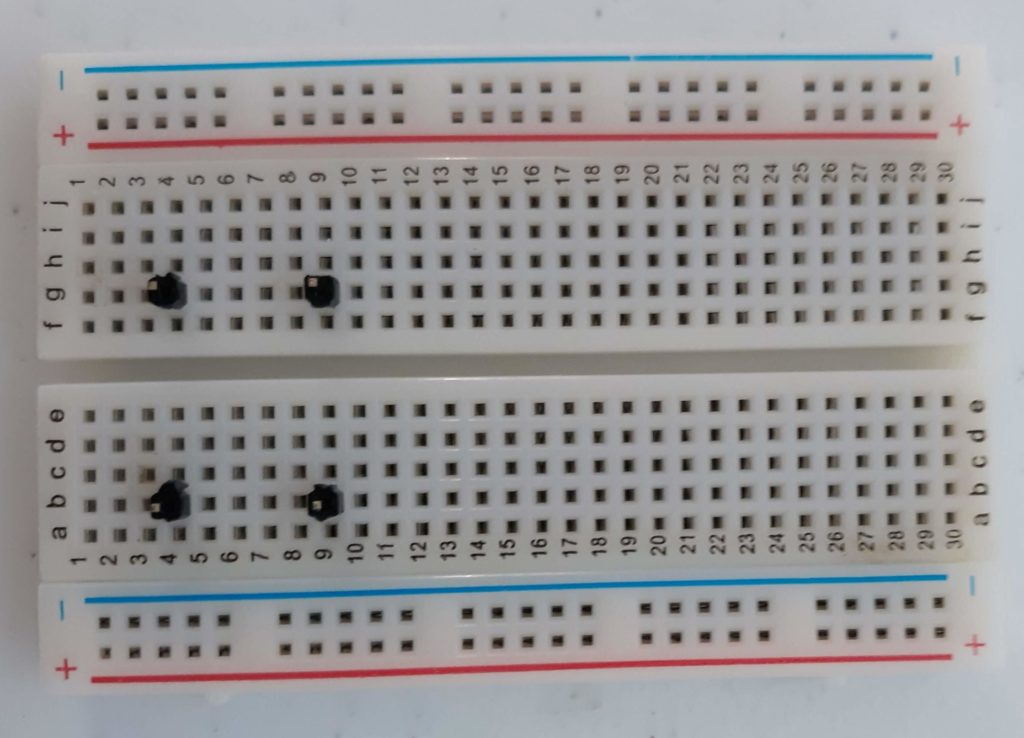
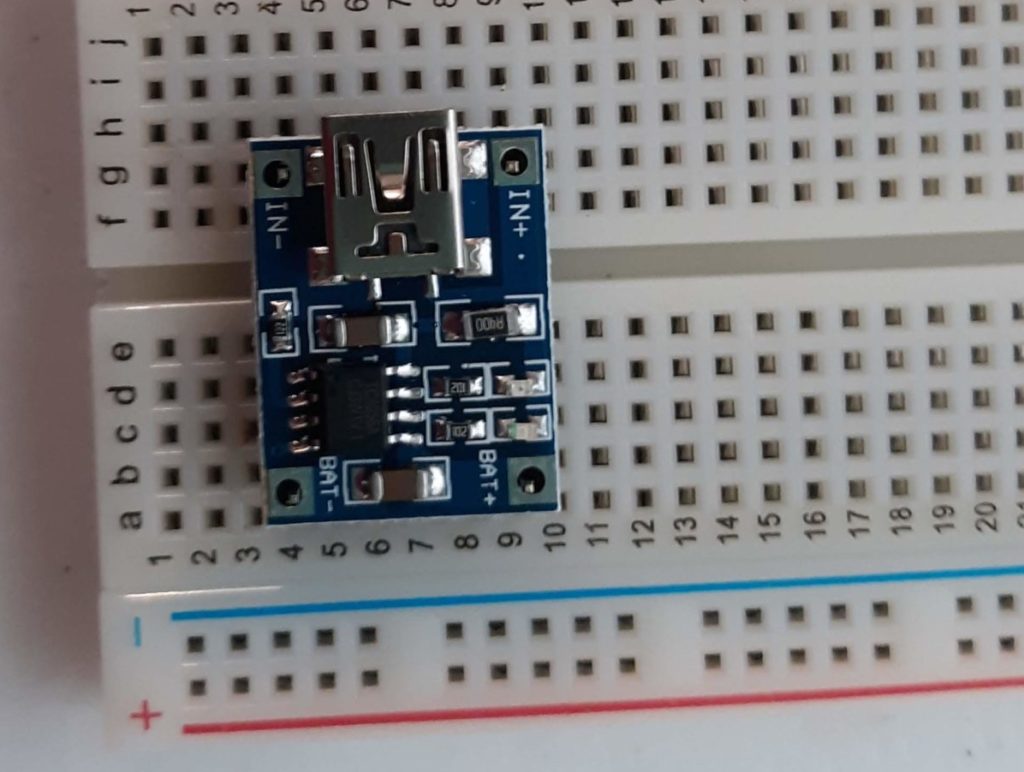
If you plan to use the battery charger and the light sensor they will need to solder header pins on them using a similar method as above.
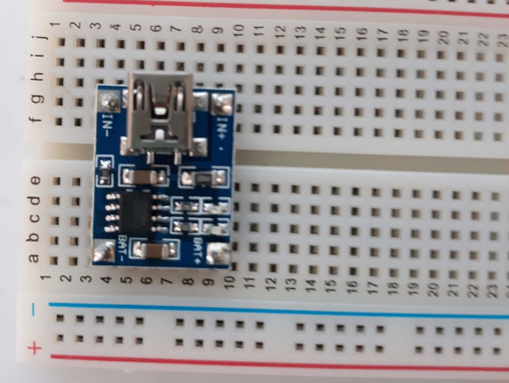
2. Position battery charger on pins. Pins used: IN+, IN-, B+ and B-
Figure 2.5
3. Solder battery holder on to header pins on breadboard
Figure 2.6
3. Create breadboard compatible connectors
While there are several components that will be ready to use right out of the box, a subset will require some assembly to attach wire ends that will enable you to plug the component directly into a breadboard. These components often come with stranded wire which is flexible and frays so it cannot be plugged into a breadboard well. The components that require new ends are the temperature sensor, thermistor and battery holder. While creating heat shrink solder connections is our preferred method, you can use any other method to connect new ends including crimping ends directly on the wires, or straight soldering of wires together.
Below are instructions for the temperature sensor. The same process can be used for the battery holder and the thermistor.
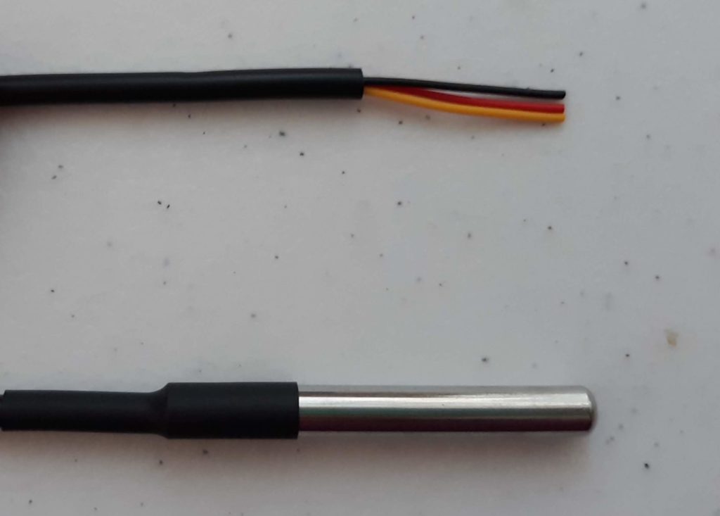
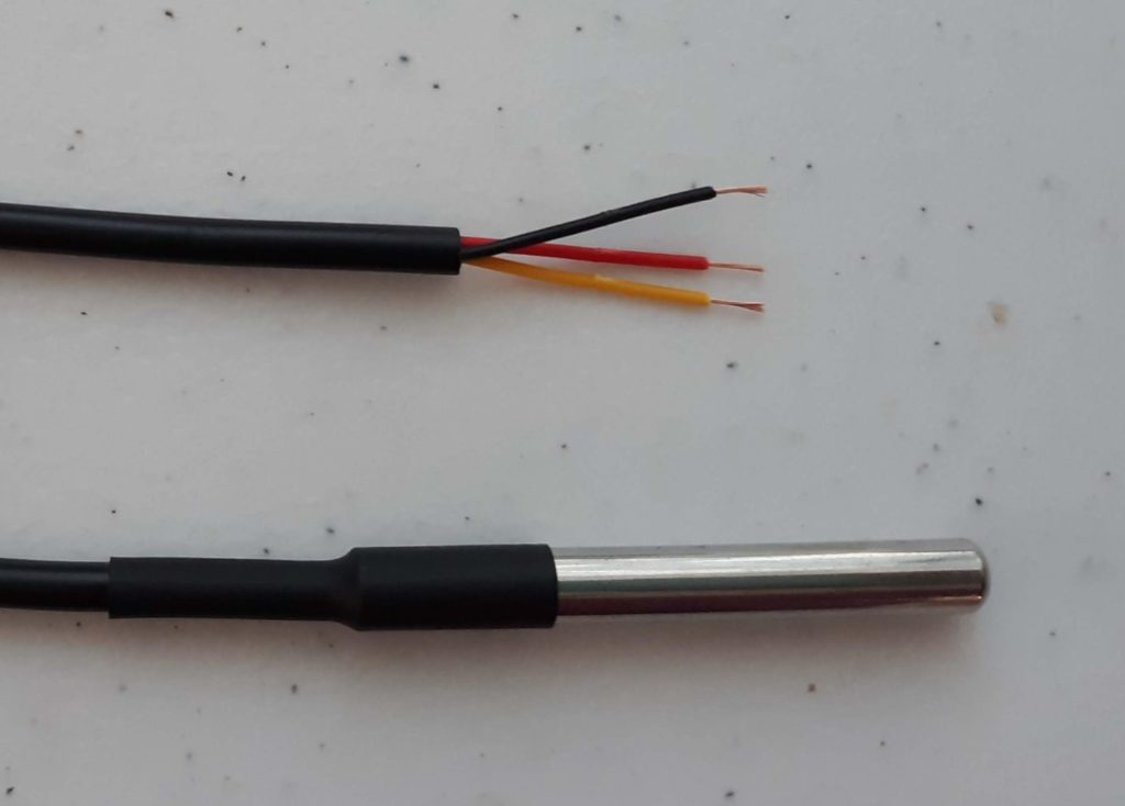
When removed from the package, the temperature sensor wires will look like Figure 3.1. They first need to be stripped such that they look like the Figure 3.2.
Figure 3.1
Figure 3.2
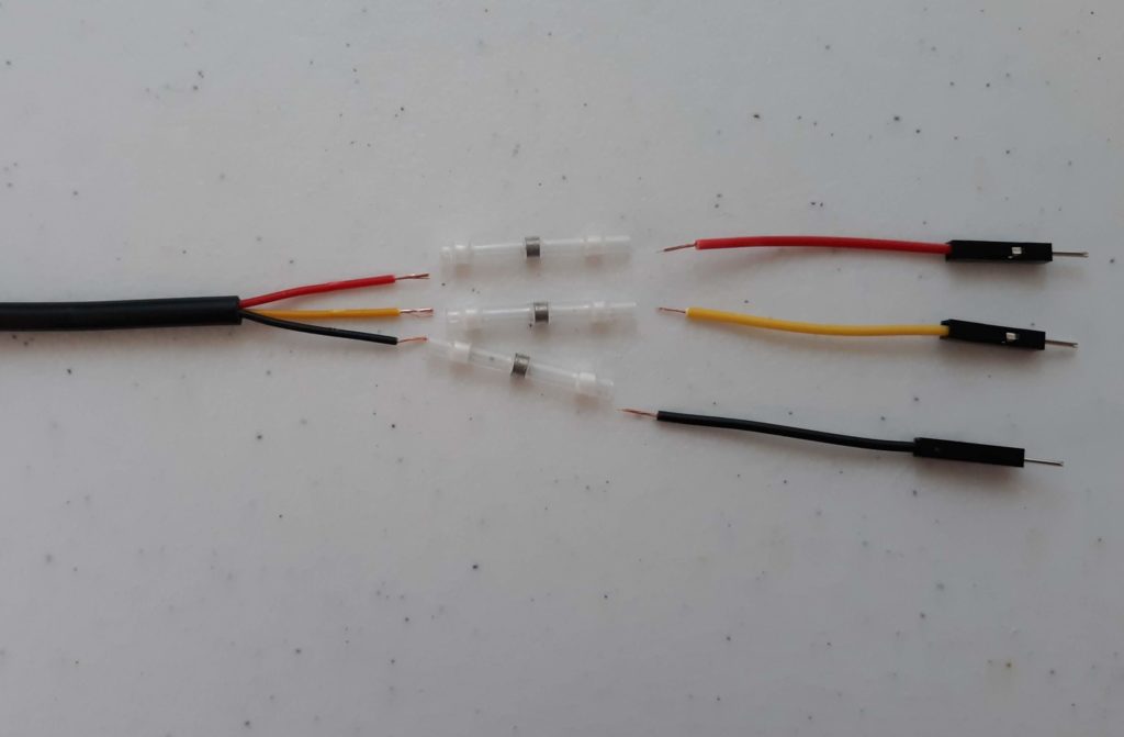
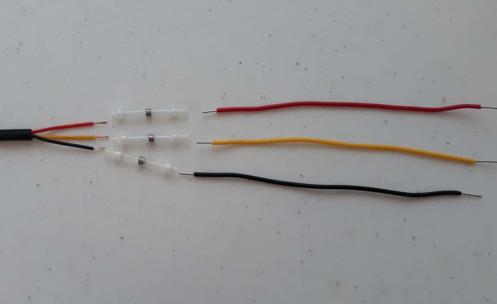
Use heat shrink solder connectors to attach new wire ends that are breadboard compatible. Options include one half of extra Male-Male jumper wires as shown in Figure 3.3, or 22 AWG Solid Core Wire as shown Figure 3.4.
Figure 3.3
Figure 3.4
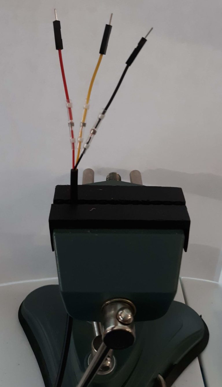
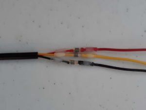
Use helping hands or a clamp to secure the position of the heat shrink solder connectors as shown in Figure 3.5. Make sure that the two stripped wire ends overlap in the the solder section of the connector. When heat is applied from the heat gun, it will melt the solder and connect the bare metal wires.
If you have not used heat shrink solder connectors before to connect wires, check out this video of the process.
If you are new to using a heat gun please make sure take precautions to you and others safe. It will get hot. Do not point it at yourself or others or other objects that are not meant to be melted.
Figure 3.5
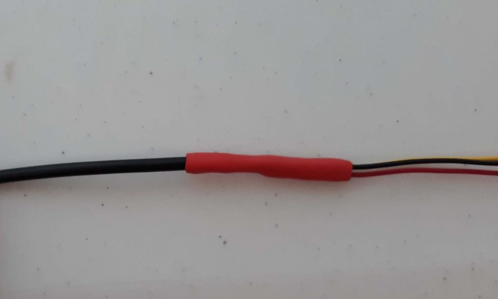
When completed, the connections should look like Figure 3.6. You may stop at this step. If you would like your connections to look cleaner, you can add a layer of heat shrink over these connections. This can help increase the durability of you materials and is good especially if using in a classroom setting or in a situation where many students will use them.
Figure 3.6
After applying the heat shrink tubing, your connections should look like Figure 3.7
Figure 3.7
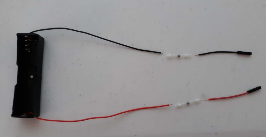
Attach Connectors to Battery Holder Wires
You will need: 3.7V 18650 Li Ion Battery holder, Male-Male jumpers or 22 AWG solid core wire, wire strippers, wire cutters, heat shrink solder connectors, heat shrink, heat gun
*Alternatively you can use 3 AA batteries and use a 3AA battery holder instead.*
Use the same procedure to add breadboard compatible connectors to the battery holder. We recommend adding female ends to the battery holder to prevent the battery from shorting while it is not plugged into the breadboard and/or in the kit box. (Figure 3.8).
Figure 3.8
4. Prepare the Kit Box (optional)
These instructions show you how to assemble all parts into a PublicSensors kit. This is optional. Educators may find it helpful to organize kit materials for student use as we have done. Educators should feel free to iterate on the kit box design only using the components most relevant for their classes.
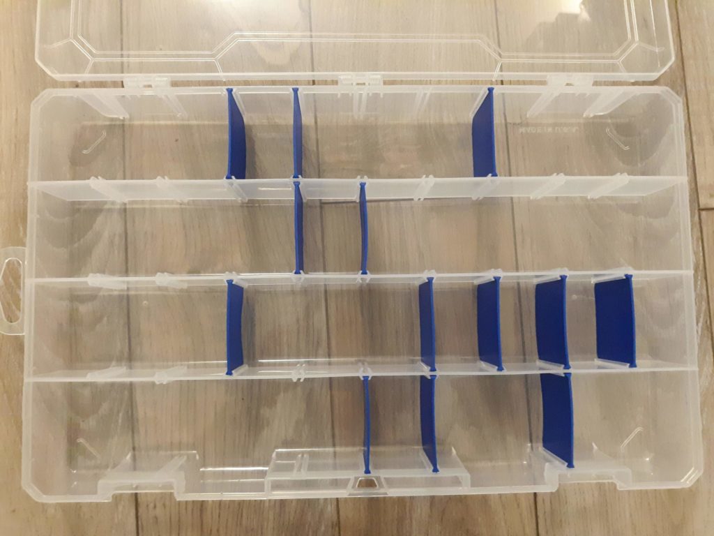
Start with the plastic organizer that will hold all of the sensor building materials.
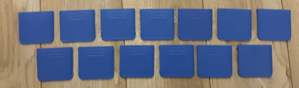
Grab the connected dividers that come with the organizer and cut them apart.
Select 13 dividers and place them in the positions pictured in Figure 4.2. This configuration will enable all 18 kit parts to fit in the plastic organizer
Figure 4.1
Figure 4.2
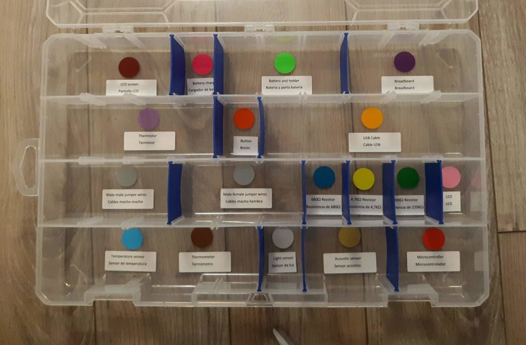
Grab the colored sticky dots and add them to the organizer sections to designate places for sensor parts as shown.
Print labels for each section using the label template. The labels contain both English and Spanish translations for the kit components. Add labels below the colored dots as shown in the photo to the right. For small sections (battery charger, button, resistors, LEDs and light sensor) the ends of the label will need to be trimmed to fit.
Figure 4.3
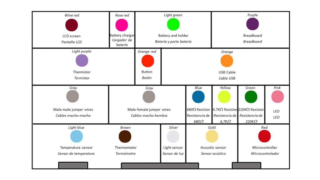
The diagram below gives more detail to set up the labeled color coded sections of the kit organizer.
Figure 4.4
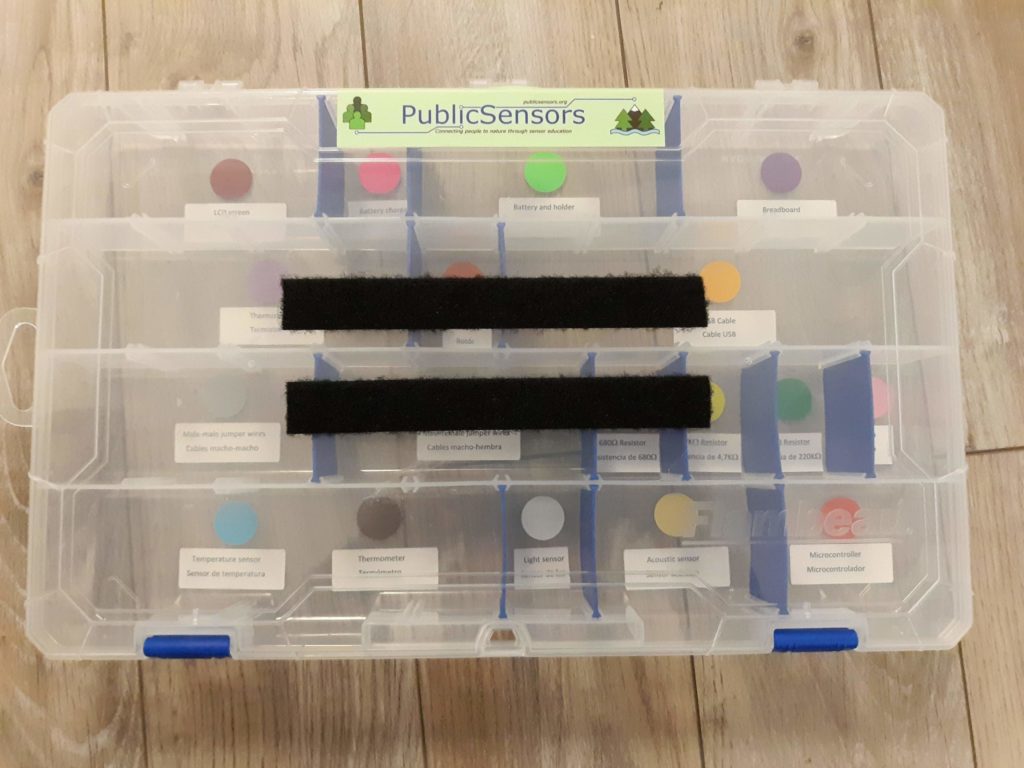
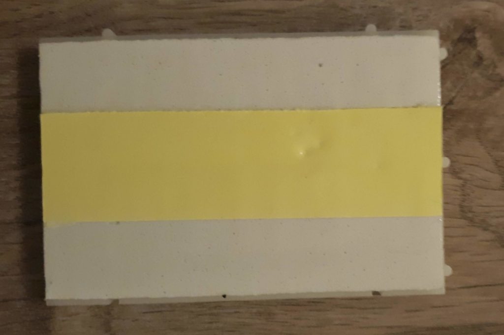
Cut two 6″ lengths of Velcro (one side). Peel of the tape and attach them to the top of the organizer box as shown. Save the length of the opposite side of the Velcro for later. The Velcro on the top of the kit box enables it to be used as a portable workstation such that components can be secured to it.
Figure 4.5
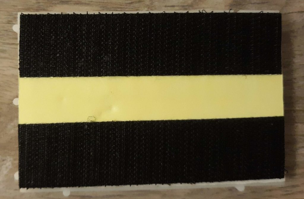
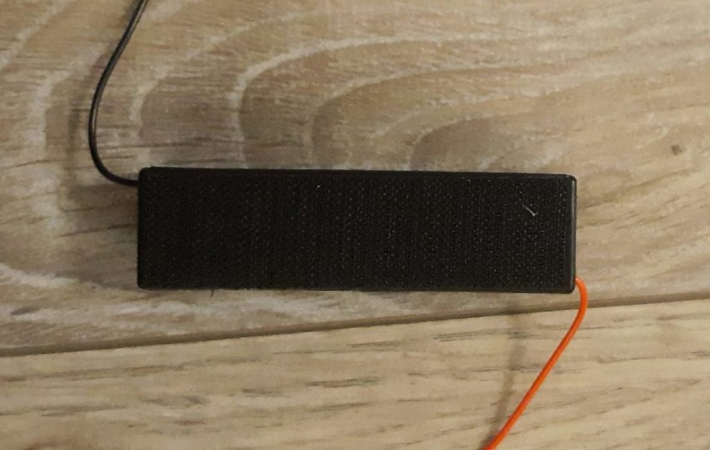
Cut 3 strips of 2″ lengths of Velcro (opposite side) to attach to bottom sides of battery holder and breadboard. Attach two strips to either side of the bottom of the breadboard and one strip to the bottom of the battery holder (Figures 4.7, 4.8). When attaching the Velcro to the breadboard, it helps to remove part of the paper covering where the Velcro will be attached (Figure 4.6) and attach it directly to the sticky pad (Figure 4.7).
Figure 4.6
Figure 4.7
Figure 4.8
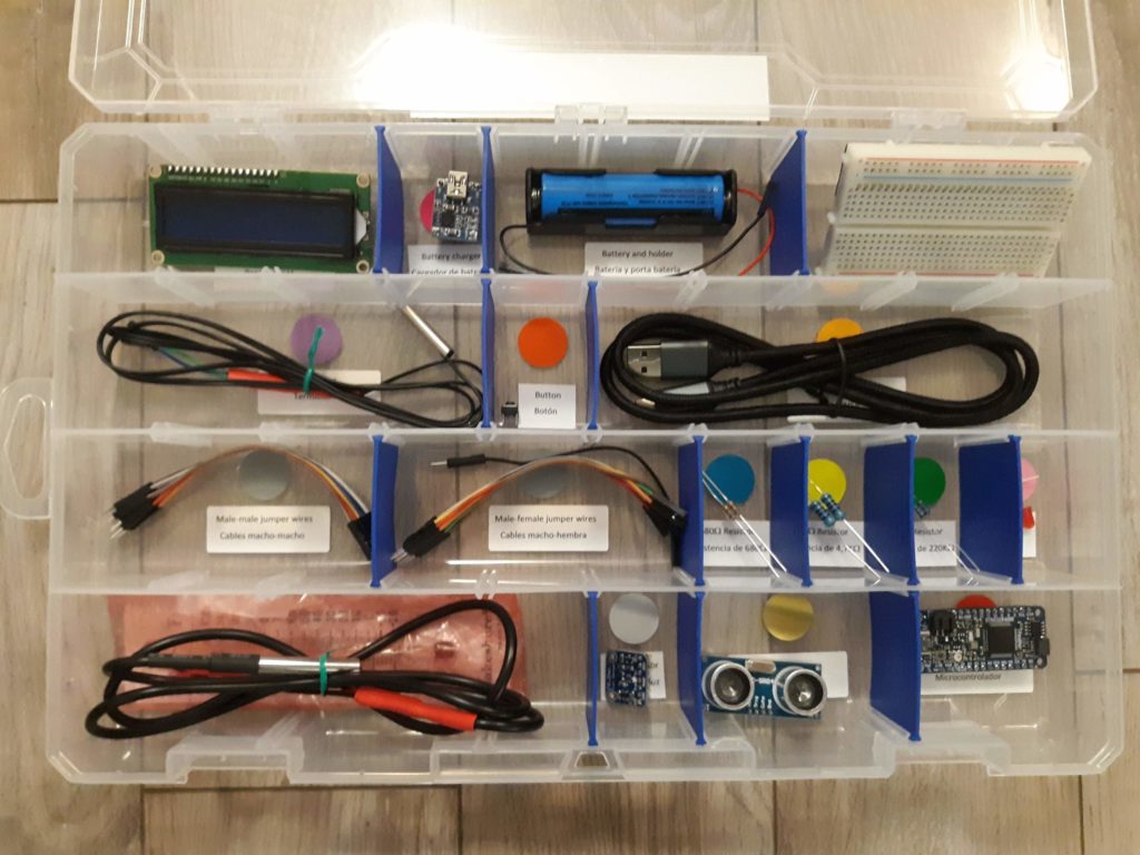
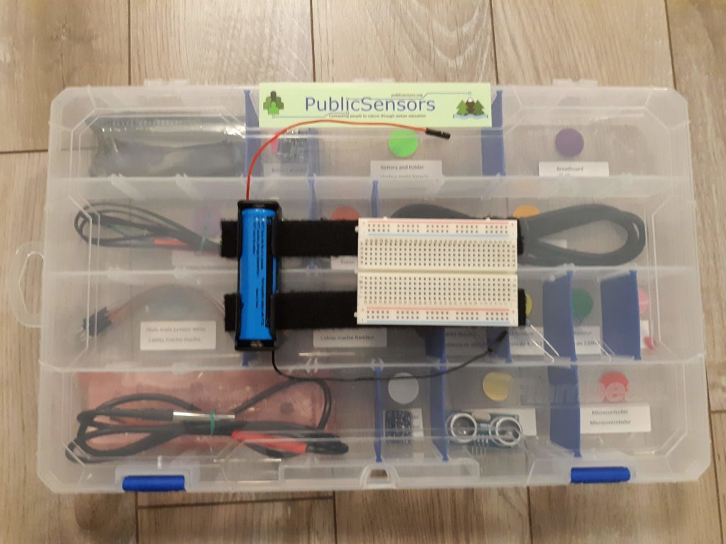
Add parts to the kit box
Add all parts to their designated spots in the kit organizer. Photos below show the the final assembled PublicSensors kit and how the Velcro is used to secure parts for sensor construction. The glass thermometer pictured is included in a bubble wrap pouch for protection.
Figure 4.9
Figure 4.10
Congratulations! You’ve constructed a PublicSensors kit!