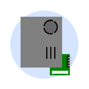
The PMS7003 particulate sensor works by measuring the light scattered by particulates in a parcel of air. The sensor uses a fan to pull air into the chamber, measures the scattering of the light, and then reports the measurement back to the microcontroller. The sensor communicated with the microcontroller using serial data protocol known as Universal Asynchronous Receiver-Transmitter, or UART. When the microcontroller sends a command, the UART converts the data into a serial stream and sends it from the TX (transmitter) pin on the microcontroller to the RX (receiver) pin on the PMS7003. When the PMS7003, it uses the same protocol to send the data back to the microcontroller from its TX pin to the RX pin on the microcontroller.
Figure 5.2
In this activity you will build an air quality sensor using the PMS7003. You can do this section without a computer and make a portable sensor, or with a computer which enables you to interact with the sensor more through the use of computer coding. Or you can try it both ways!
Note: For more information on the PMS7003 sensor, check out the sensor datasheet.
Building your PMS7003 air quality sensor
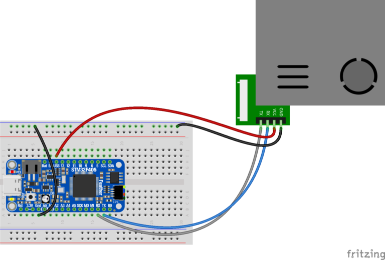
Figure 5.3
Create a circuit to read a PMS sensor from your microcontroller. Start by connecting the VCC pin on the PMS7003 to the USB pin of the microcontroller using the breadboard.
2. Connect the GND pin on the PMS7003 to your microcontroller by first connecting the GND pin on the microcontroller to the (-) rail on the breadboard using a male-male jumper wire. Then connect the GND pin on the PMS7003 to anywhere on the same (-) rail on the breadboard.
3. Connect the TX pin on the PMS7003 to the RX pin on the microcontroller.
4. Connect the RX pin on the PMS7003 to the TX pin on the microcontroller.
Note: it helps to keep the colors of the jumper wires constant to keep track of your connections. For example, all ground wires should be a black or dark color.
Setting up the LCD Screen and Button
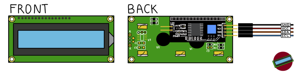
Figure 5.4
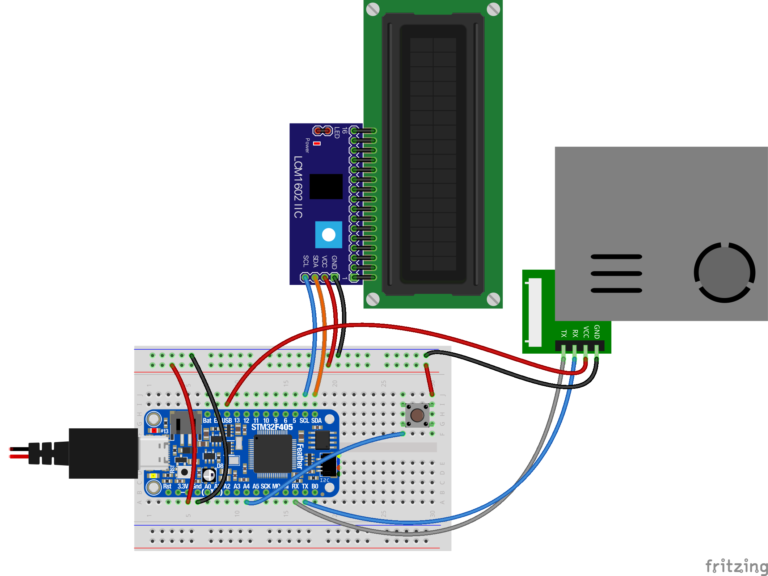
5. The LCD screen uses 4 pins that get connected to the microcontroller. Use male-female jumper wires to make these connections (See Figure 2.5 below):
a. Connect VCC on the LCD to the (+) rail on the breadboard. b. Connect GND on the LCD to GND on the microcontroller c. Connect SDA on the LCD to SDA on the microcontroller d. Connect SCL on the LCD to SCL on the microcontroller
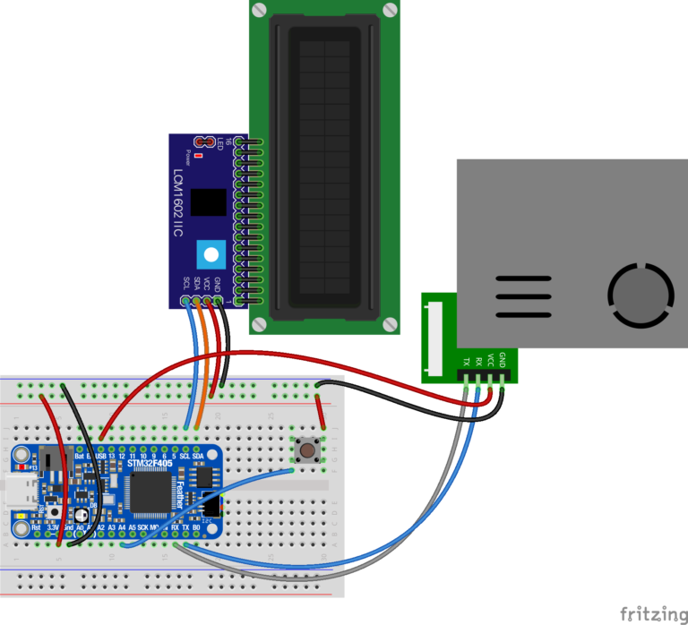
6. Connect 3.3V on the microcontroller to the (+) rail on the breadboard using a male-male jumper wire. This will power the LCD.
7. Connect your button. Connect one side of the button to the (+) rail on the breadboard using a jumper. Connect the other side of the button to Pin A4 on your microcontroller using a second jumper.
Figure 5.5
Before connecting the microcontroller to power, double check all of your connections to make sure it matches the diagram above (Figure 5.5).
8. The PMS7003 needs 5v to run, so instead of using a standard battery, the microcontroller must be powered using 5+V which can be accomplished by using the USB cable, powering the microcontroller by plugging it into a computer or portable power pack.
Figure 5.6
9. You can start taking measurements once the LCD display changes and displays “Ready!” after 5-10 seconds. To take a single temperature measurement, press the button once. A temperature measurement in degrees Celsius will appear on the first line of the LCD screen.