In this activity, you will design, assemble, and calibrate an analog temperature sensor using a thermistor. An analog signal is something that can continuously vary, like voltage. In the DS18B20 activity, the temperature sensor sent a digital, or discrete (single value), signal to the microcontroller. In this activity, we will be measuring voltage that continuously changes as it flows through the sensor. Instead of sending a digital signal of temperature to the microcontroller, we will calculate the resistance of the thermistor as it changes with temperature, which you will then use to create a calibration curve (as shown in Figure 2.1).
In addition to materials in your PublicSensors kits, you will need a waterproof thermistor that you can connect to the breadboard using the jumper cables in you kit.
Use the procedure linked here to attach breadboard compatible connectors to the thermistor wires.
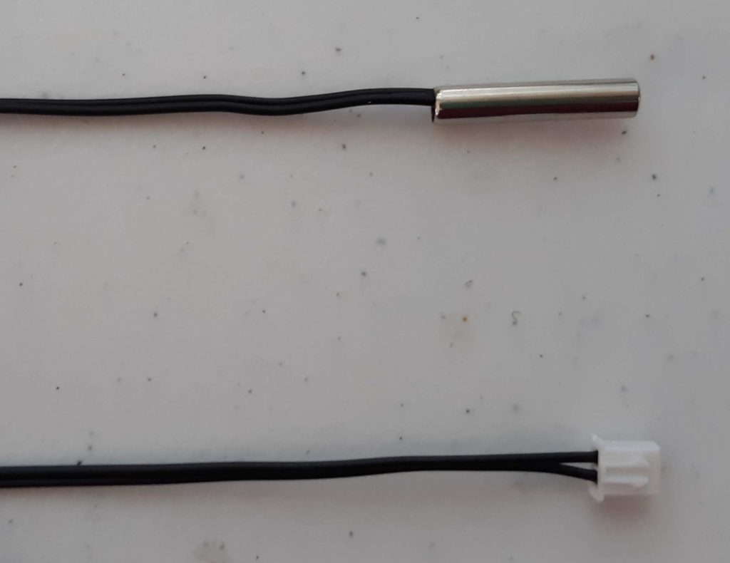
The thermistor comes with two female ends which can be connected to the breadboard using Male-Male jumper wires. If you keep the original thermistor connector, be aware you will need two more Male-Male jumpers to attach it to the breadboard. If you would like to add male ends to the thermistor, use the procedure described above and the steps below.
1. Image of the original thermistor female ends
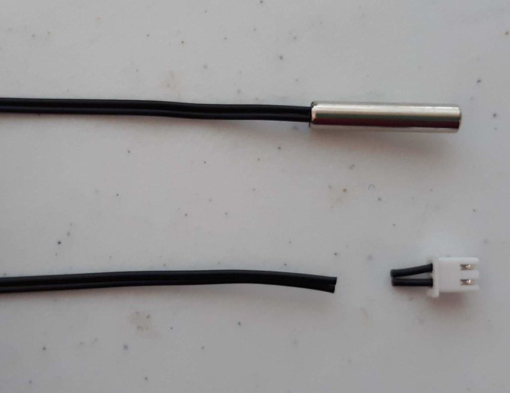
2. Remove original end wire wire cutters
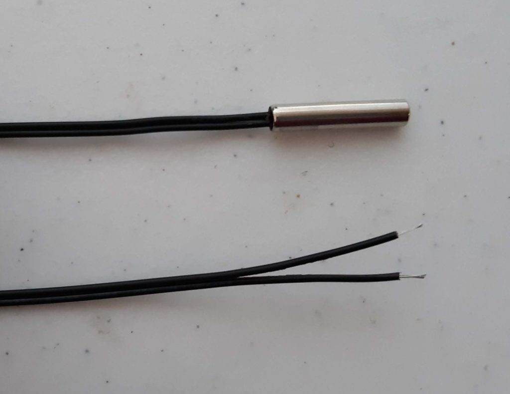
3. Strip wire ends using wire strippers
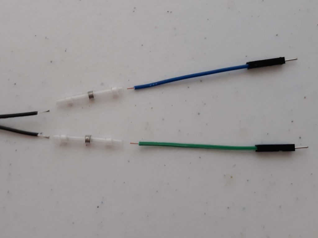
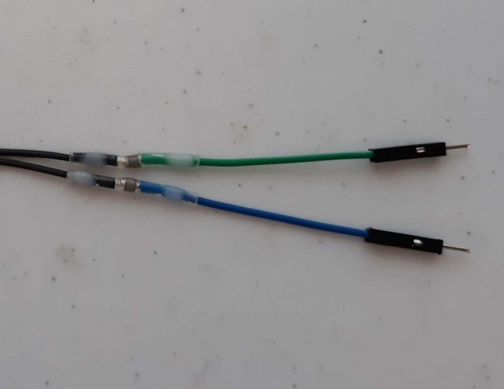
4. Prepare new wire ends and solder connectors
5. Use heat gun to connect new wire ends
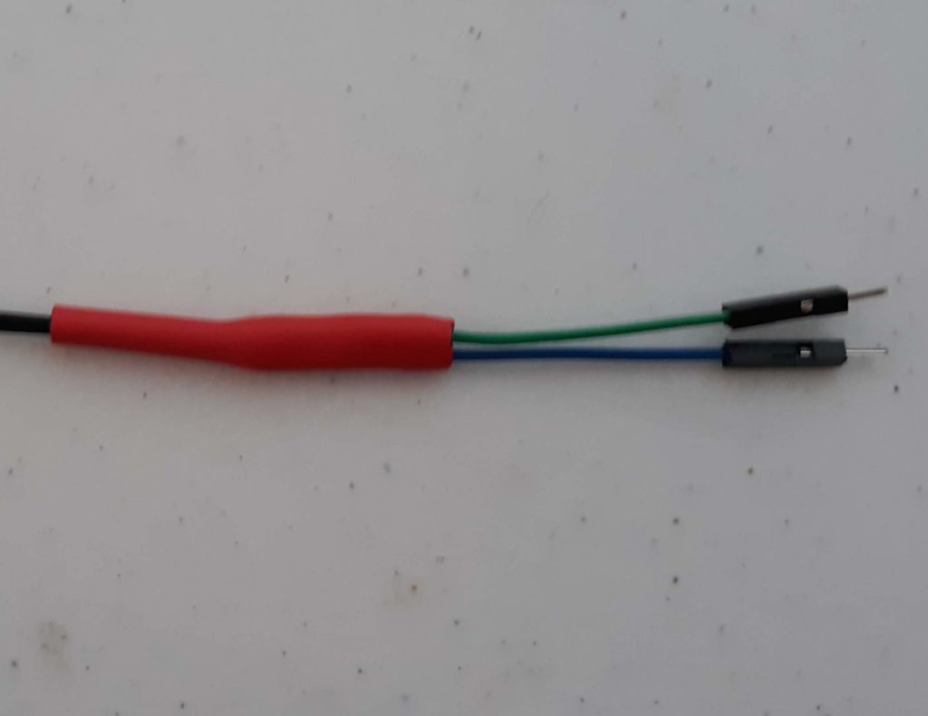
6. Cover new connections with heat shrink
Figure 3.9
Figure 3.10
Figure 3.11
Figure 3.12
Figure 3.13
Figure 3.14
Building the circuit
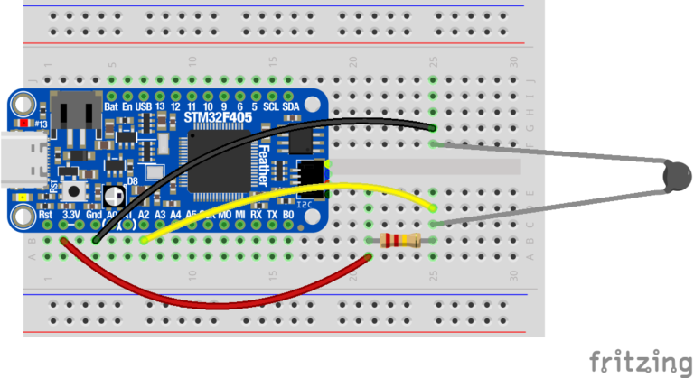
Create a circuit using the waterproof thermistor that will enable you to measure the changes in resistance as the temperature changes. You’ll want to begin with an empty breadboard with only your microcontroller connected.
Figure 2.8
1. Start by connecting a 220 KΩ resistor (this will be the R1 value in the calculations in the code below) to the 3.3V pin on your microcontroller (this will be the V1 value).
2. Connect the other end of the 220 KΩ resistor to one end of your thermistor which will be R2.
3. Connect the other end of the thermistor to the GND pin on the microcontroller by having both pins connected to the (-) rail on your breadboard (this is V3 in the diagram above).
4. To measure the voltage at the connection between the 220 KΩ resistor and the thermistor (V2), use a jumper to connect where the two resistors meet to the A2 pin on your microcontroller. This pin will be used as the “ADC” pin, which stands for “Analog to Digital Converter”, and converts voltage to a digital number.
Measure the voltage
5. Connect your microcontroller to your computer using the USB cable. When the microcontroller folder appears, check that the following file is in the folder:
thermistor_calcs.py
If you are missing the file, you can download it from the Code Resources page to your computer and copy it to the microcontroller folder.
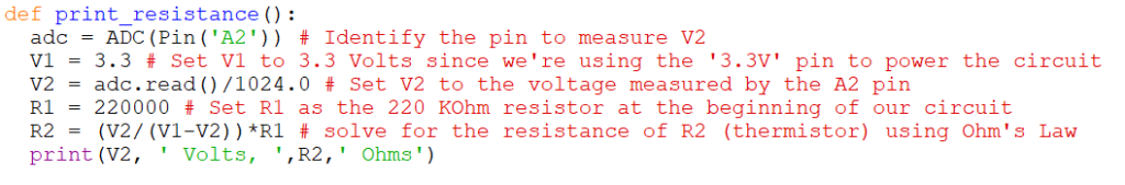
thermistor_calcs.py is the python function that will use the voltage at V2 measured by the ADC pin to calculate the resistance across the thermistor. The code looks like the following:
Figure 2.9
6. Open the Beagle Term Chrome App (for additional instructions on setting up Beagle Term, see the Beagle Term Guide on the Sensor Help page) and type “import thermistor_calcs” and press enter.
7. On a new line in Beagle Term, type “thermistor_calcs.print_resistance()” and press enter. Beagle Term will print the voltage measured by the ADC pin followed by the calculated resistance of the thermistor.
Reminder: To disconnect the microcontroller from the computer, do not just unplug it! Eject it as you would a flash drive and make sure it is safe to eject.
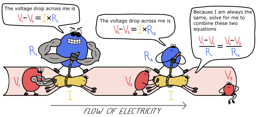
Bonus: How does the thermistor circuit actually work?
For your thermistor-based sensor, you created a circuit to measure a change in voltage, and converted it to resistance to determine temperature. To understand why this works, recall Ohm’s Law (from Introduction to Circuits) which describes the relationship between voltage (V), current (I) and resistance (R) as V=IR. Remember, that voltage refers to the voltage drop across a resistor. The type of circuit you created with your thermistor is called a voltage divider. A voltage divider, drawn in the diagram below, is a circuit where two resistors (R1 and R2) are used to reduce voltage as electricity flows through a wire. We can use Ohm’s Law to figure out the voltage drop across each resistor or solve for quantities that we don’t know using the equations below.
Figure 2.10
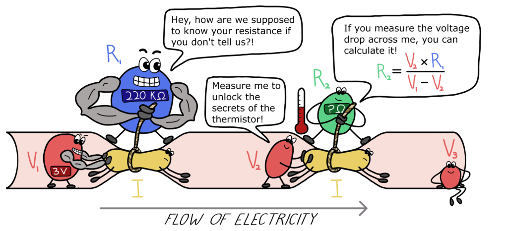
But how does Ohm’s Law help us measure temperature? A thermistor is a type of resistor, so we can replace one resistor in the voltage divider with a thermistor and use the same equations. Because the resistance of the thermistor is based on temperature, we often don’t know its resistance, but we can solve for it by measuring the voltage drop across it (V2).
Figure 2.11
You used your microcontroller to measure the voltage drop across the thermistor (V2). You provided a known voltage into the circuit (V1 = 3V) and used a known resistance for the first resistor (R1 = 220 KΩ) to calculate the resistance of your thermistor. With this method you can now investigate how thermistor resistance changes with temperature.
For more information on Ohm’s Law and voltage dividers, check out the PublicSensors Textbook.