Understand the basic electrical quantities and the relationships between them
Develop skills in building simple circuits
Develop skills in using a breadboard to make simple circuits
Time required: 30 minutes
Prerequisite skills: None!
Materials Needed:
Introduction to Electricity:
When we create circuits, we direct electricity to flow in a continuous and specific path, typically along a wire or many connected wires. Circuits receive an input of electricity from a power source like a battery or a computer. Electricity flows through the circuit and then is returned to ground. All circuits have a power input (typically a red wire, positive end) and a ground output (typically a black wire, negative end). Before building circuits it is important to understand a few components of them.
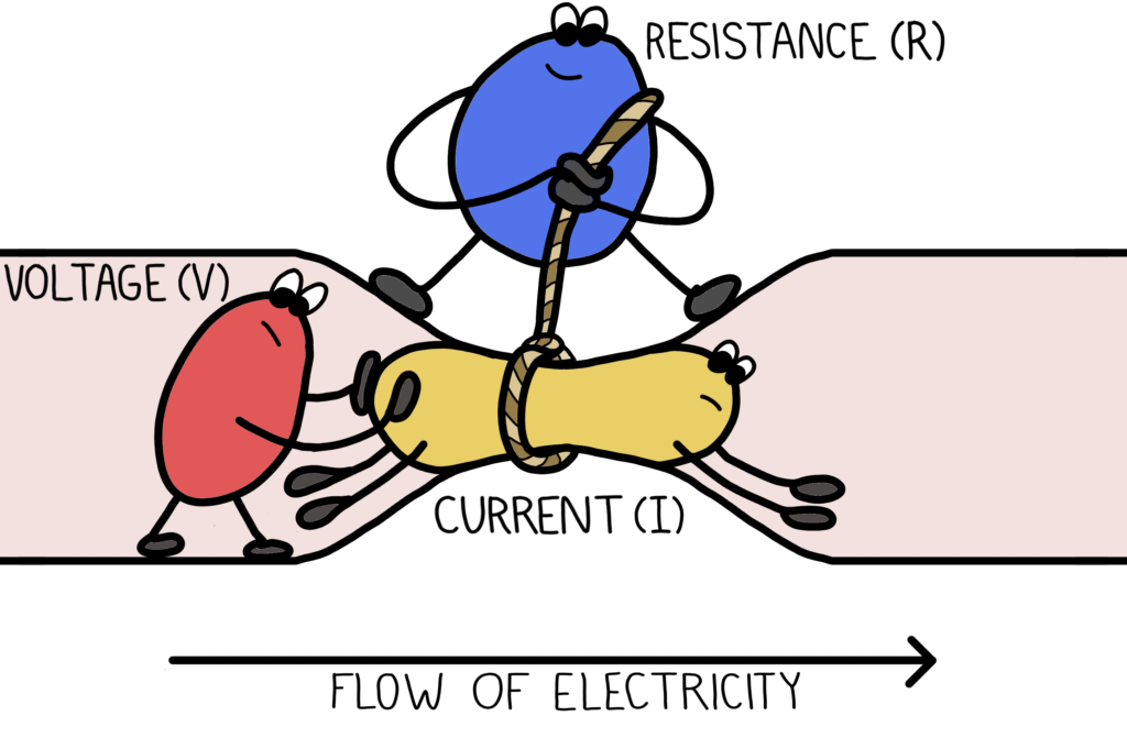
Figure 1.1
The force that moves electricity through a conductor, like a wire, is called voltage. The rate that electricity flows through the wire is called current. As the electricity flows through the wire, it can be slowed down by resistance. More resistance means that more voltage is needed to send current through the wire. You can change the resistance by adding resistorsalong the wire.You can change the voltage by changing the power source or battery strength.
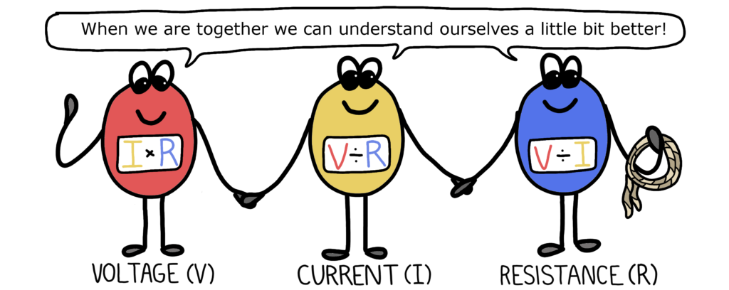
Voltage is measured in volts (V). Current is measured in Amperes (Amps). Resistance is measured in Ohms (Ω). These three components of circuits are related to each other. The relationship between voltage, current, and resistance is defined by
Voltage (V) = Current (I) x Resistance (R).
This equation is known as Ohm’s Law. If we know any two of the three quantities, we can calculate the missing one.
Figure 1.2
Audio Read Along: Introduction to Electricity
Circuit Building Basics:
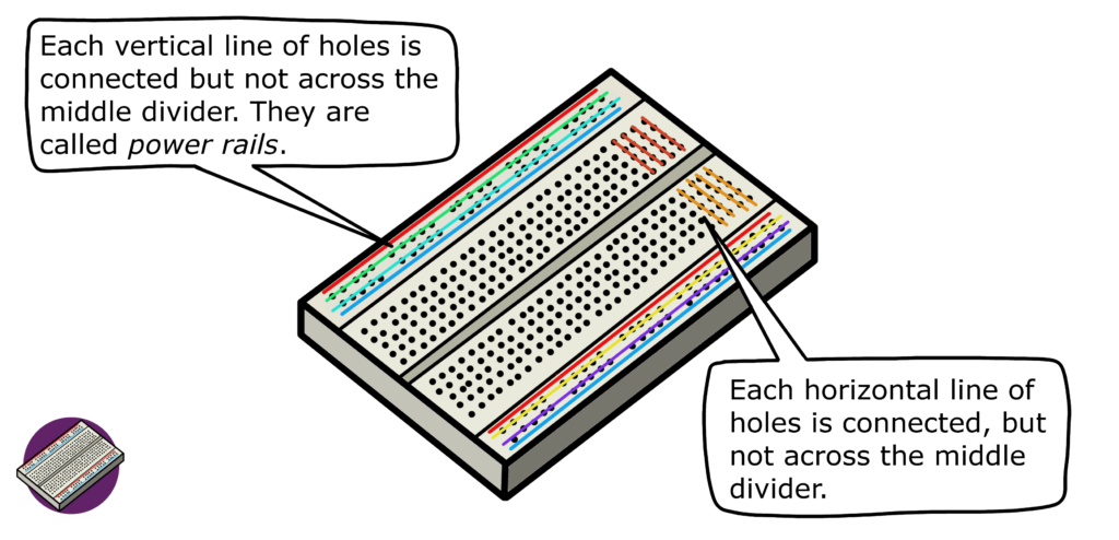
To assemble a circuit you will need to use a breadboard which lets you connect wires of your circuit together. To make electrical connections on a breadboard, we use jumper wires, which have ends that easily fit into the hole on a breadboard. Horizontal rows of 5 holes are connected so that if you want to connect multiple wires in a circuit, plug them into holes in the same row. Likewise, if you plug wires into the holes along a vertical line, they will be all connected. In this first circuit building activity, you will use a breadboard to create a circuit that powers an LED.
Figure 1.3
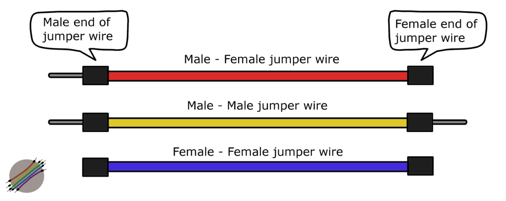
Jumper wires help connect circuits made on a breadboard. Jumper wires are characterized by the type of ends they have, usually referred to as male or female ends. For example, a jumper wire can have two male ends, one male and one female, or both female. Male ends can be plugged directly into the breadboard.
Figure 1.4
Audio Read Along: Circuit Building Basics
Build a Simple Circuit:
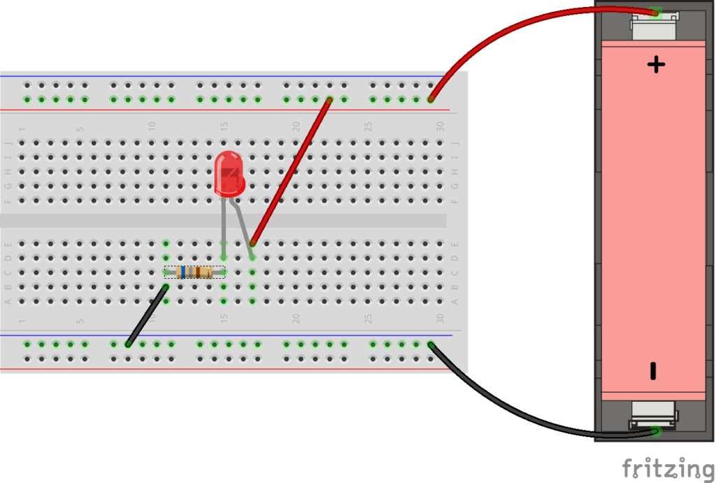
You will build a simple circuit that powers an LED using the following diagram. Step by step instructions are below.
Figure 1.5
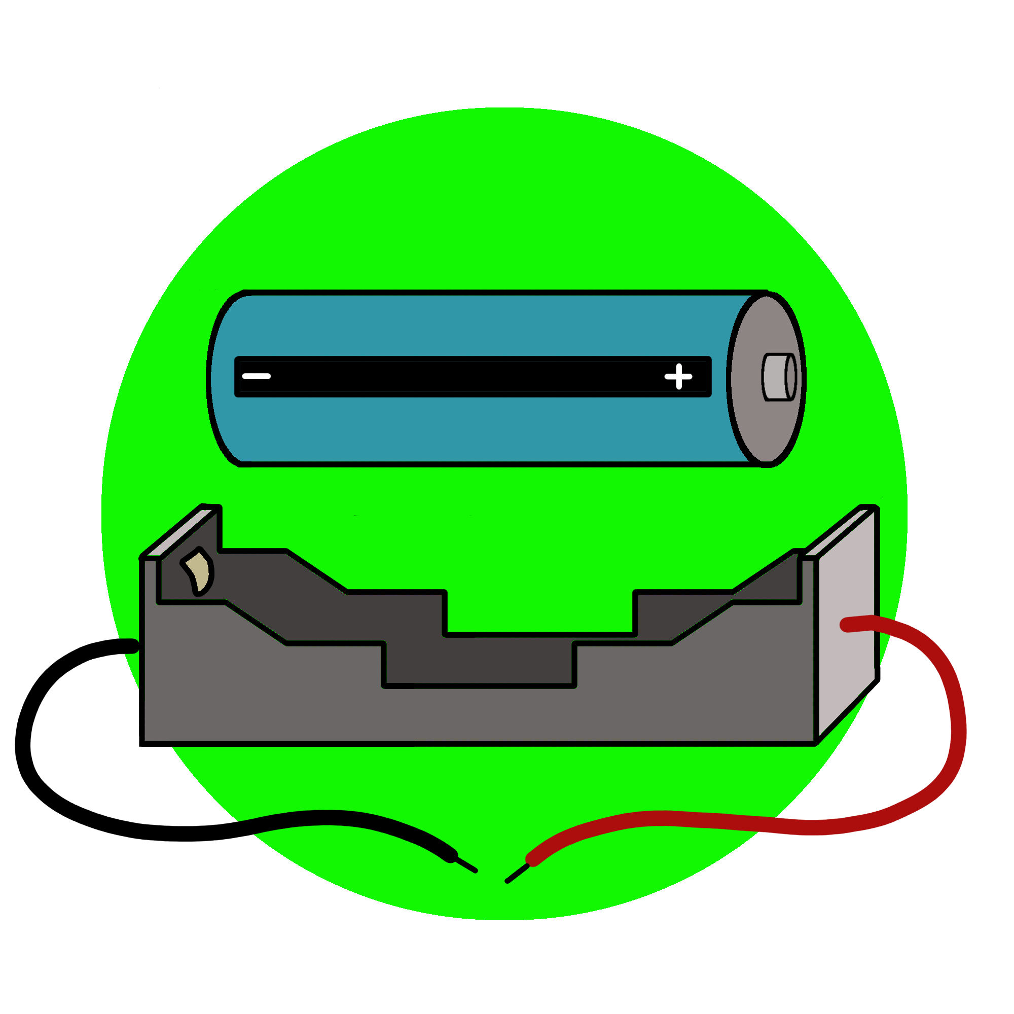
Attach the positive (red wire) of the battery to the end of one (+) power rail on the breadboard
Attach the negative (black wire) of the battery to the end of one (-) power rail on the opposite side of the breadboard.
Connect the positive rail to a row of holes on the breadboard using a male-male jumper.
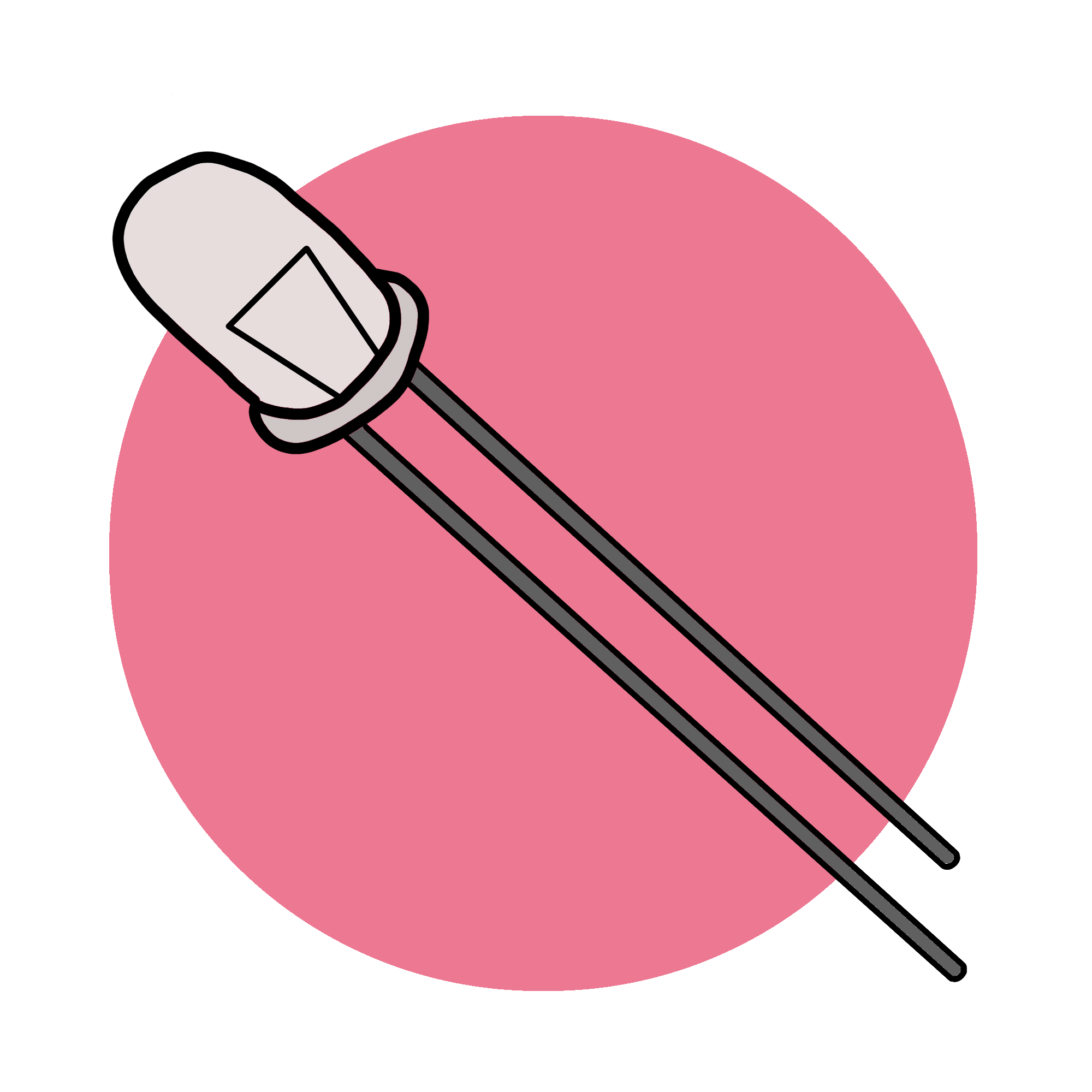
Put the LED into the breadboard. The longer end is the positive end and it should be inserted into the same row as the jumper you just connected to the positive rail.
Connect one end of a 680Ω resistor to the row with the negative end of the LED. Connect the other end to an empty row on the breadboard.
Complete the circuit using a male-male jumper to connect the row with the other end of the resistor to the negative power rail.
If your battery is fully charged, the voltage of your circuit is 3.7 volts. The resistor in your circuit is 680Ω. Can you calculate the current? Refer to Figure 1.2 if you need help.
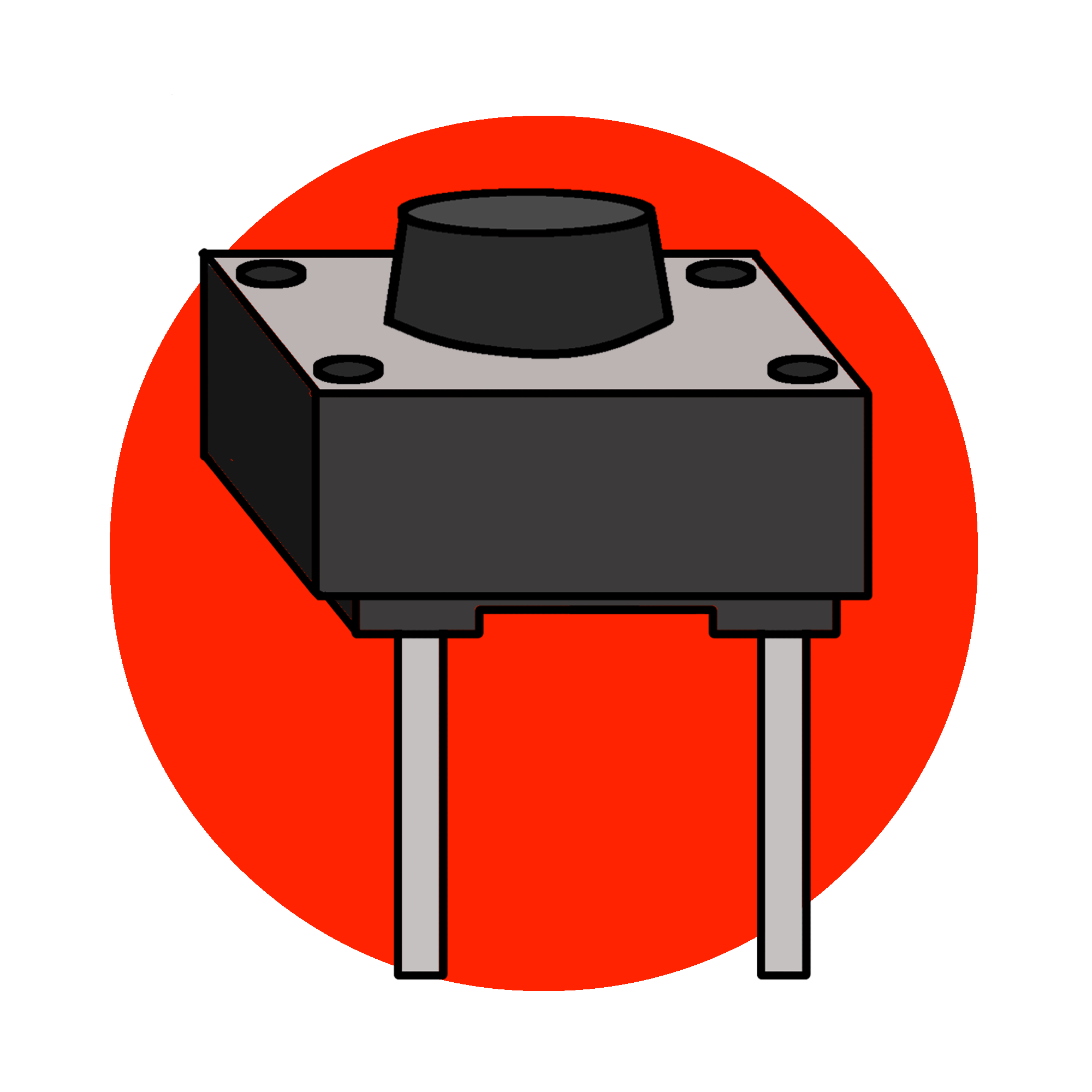
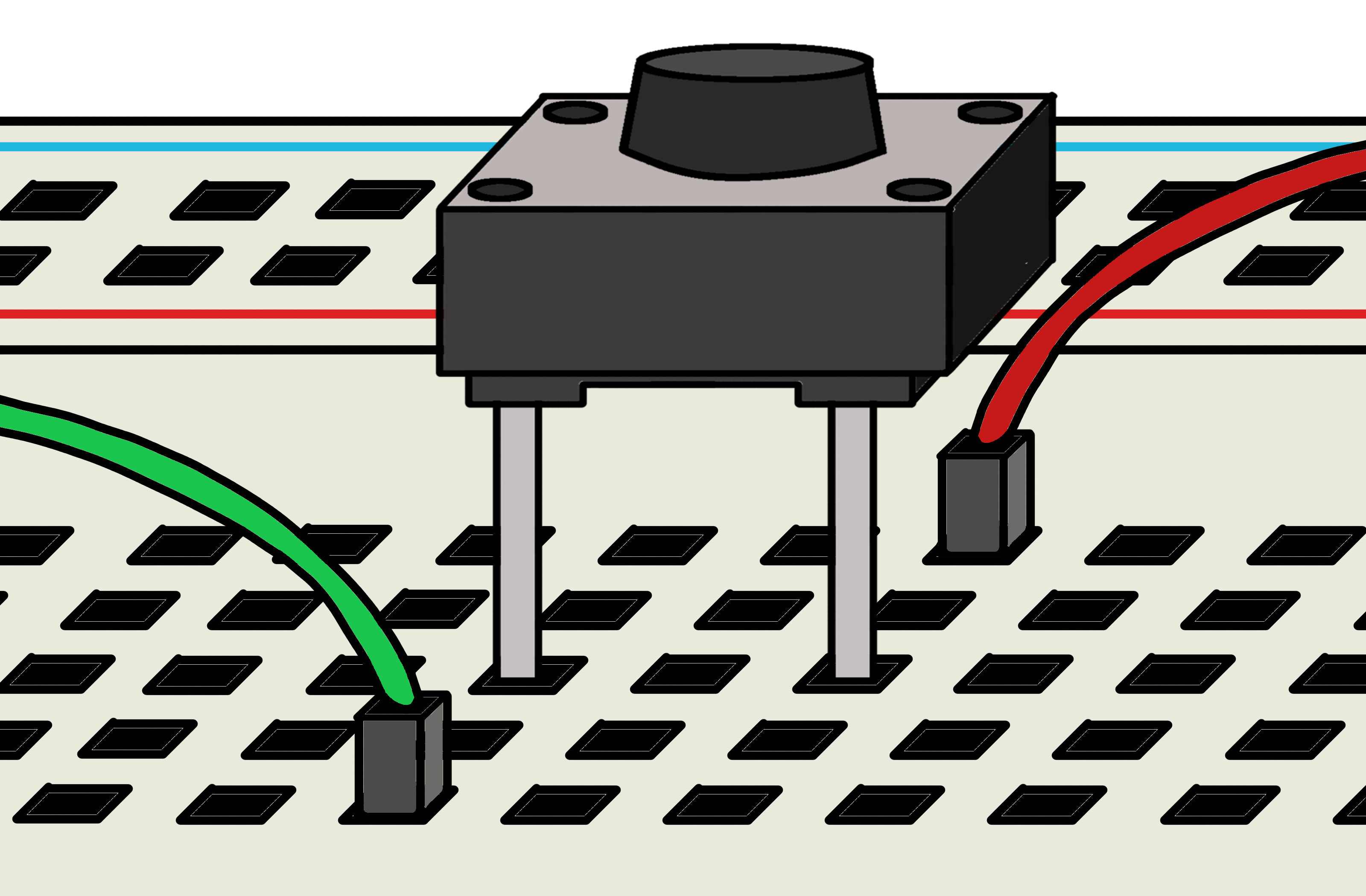
Now what if we want to blink the LED? The LED stays on because electricity is continuously running through it. To blink the light, we need to momentarily stop the flow of electricity through the circuit and start it again. For this we can use a button. When the button is pressed down, it completes the connection in the circuit and the LED turns on. When the button is released, it interrupts the connection and turns the LED off. Use the diagram below to help you put the button into the breadboard in the correct orientation.
Figure 1.6
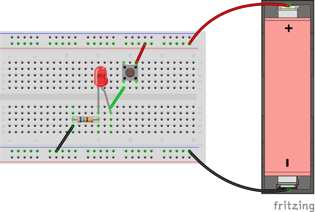
We can set up the same circuit as we did above but add a button between the (+) power rail and the positive end of the LED. Use the diagram below to add the button.
Figure 1.7
Push the button down. The LED should light up! Release the button. The LED should turn off!
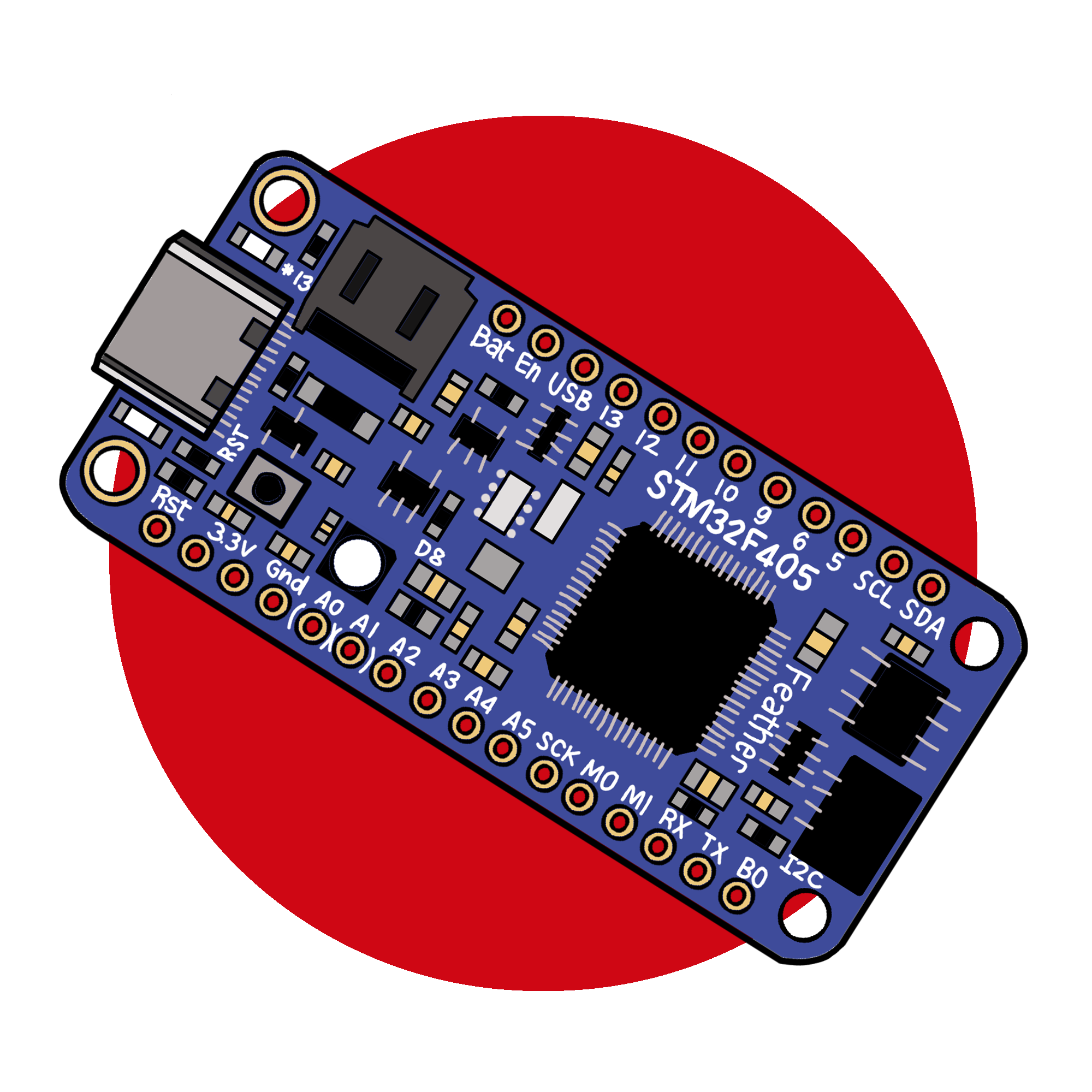
What if you wanted to blink the LED 30 times? That would be a lot of button pushing! This is where your microcontroller comes in. A microcontroller can use code to automate these actions. The next steps will get you familiar with using a microcontroller, and help you set up a similar LED circuit using one.