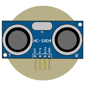
The HC-SR04 ultrasonic distance sensor works by transmitting a pulse of sound and listening for the echo. The sensor consists of two ultrasonic transducers. Ultrasonic refers to the frequency, 40 kHz (40-thousand cycles per second), which is a higher pitch than humans are capable of hearing. One transducer acts as a transmitter which converts electrical signal into pulses of sound when a signal is received by the “Trigger” pin. The receiver listens for the echo of the transmitted sound pulses. If it receives them, it produces an output signal sent to the “Echo” pin. The time between when the signal is sent and received is used to determine the distance the sound pulse traveled as explained above.
Figure 4.2
In this activity you will build a distance sensor using the HC-SR04 . You can do this section without a computer and make a portable sensor, or with a computer which enables you to interact with the sensor more through the use of computer coding. Or you can try it both ways!
Note: For more information on the HC-SR04 sensor, you can see the sensor datasheet.
Building your HC-SR04 ultrasonic distance sensor
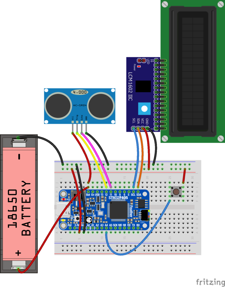
Figure 4.3
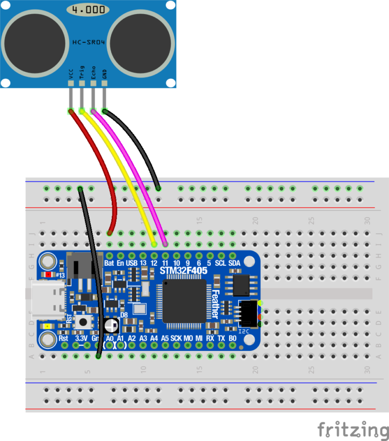
Create a circuit to read an HC-SR04 sensor from your microcontroller. Start by connecting the VCC pin on the HC-SR04 to the BAT pin of the microcontroller.
Connect the GND pin (black wire) on the HC-SR04 to your microcontroller by first connecting the GND pin on the microcontroller to the (-) rail on the breadboard. Then connect the GND pin on the HC-SR04 to anywhere on the same (-) rail on the breadboard.
Connect the TRIG pin on the HC-SR04 to Pin 12 on the microcontroller.
Connect the ECHO pin on the HC-SR04 to Pin 11 on the microcontroller.
Note: it helps to keep the colors of the jumper wires constant to keep track of your connections. For example, all ground wires should be a black or dark color.
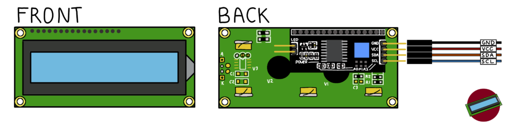
Setting up the LCD Screen and Button
Figure 4.4
5. The LCD screen uses 4 pins that get connected to the microcontroller. Use Male-Female jumper wires to make these connections (See Figure 4.5 below):
a. Connect “VCC” on the LCD to the “(+)” rail on the breadboard. b. Connect “GND” on the LCD to “GND” on the microcontroller c. Connect “SDA” on the LCD to “SDA” on the microcontroller d. Connect “SCL” on the LCD to “SCL” on the microcontroller
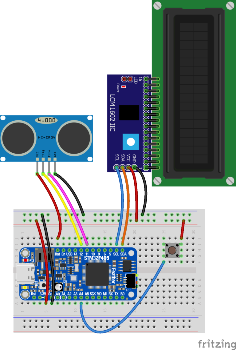
6. Connect “3.3V” on the microcontroller to the “(+)” rail on the breadboard using a male-male jumper wire. This will power the LCD.
7. Connect your button. Connect one side of the button to the (+) rail on the breadboard using a jumper. Connect the other side of the button to Pin “A4” on your microcontroller using a jumper.
Figure 4.5
8. Before connecting the microcontroller to the battery, double check all of your connections to make sure it matches the diagram above (Figure 4.5).
9. Insert the battery into the battery holder so that the positive side, indicated by the “+” symbol, is on the side of the holder with the red wire, and the negative side of the battery is on the side of the holder with the black wire.
10. Connect the black wire from the battery holder to the “GND” pin on the microcontroller. You can also do this by connecting the black wire from the battery holder to the “(-)” rail that the microcontroller “GND” pin is also connected to.
11. Connect the red wire from the battery holder to the pin labeled “BAT” on the microcontroller (see Figure 4.6 below). Once the battery is connected, the LCD should light up and display “Hello!”. For instructions on charging the battery, see the Charging the Battery page.
Figure 4.6
10. You can start taking measurements once the LCD display changes and displays “Ready!” after 5-10 seconds. To take a single distance measurement, press the button once. A distance measurement in cm will appear on the first line of the LCD screen.
11. To stop powering the instrument, remove the red battery wire from the “BAT” connection. To try using it with a computer, remove the battery connections and follow the directions below.